


You order a replacement impeller with the same outside diameter and material as the old one. It fits the shaft. It clears the casing. But the pump never returns to the curve. Flow drops. Power climbs. The seal fails early. The real problem wasn't the diameter — it was the vane geometry, clearance design, and the fact that the original impeller had already been trimmed once. This article gives you the engineering map to avoid that scenario. You will learn what centrifugal pump impellers actually do, how the main types differ, what each variable changes on the pump curve, and what to inspect before you trim, replace, or upgrade.
Key Terms
– Impeller eye: The inlet opening at the center of the impeller where liquid enters the vane passages.
– Vane: A curved blade on the impeller that transfers energy to the fluid and guides flow from the eye toward the impeller outside diameter.
– Shroud: The disc-like wall on the front and/or rear of the impeller that encloses the vane passages.
– Volute: The spiral casing section that collects discharge from the impeller and converts velocity into pressure.
– BEP (Best Efficiency Point): The flow rate at which the hydraulic design operates with maximum efficiency.
– POR / AOR (Preferred / Allowable Operating Region): The flow ranges defined by ANSI/HI 9.6.3 where the pump operates reliably; POR is tighter than AOR.
– NPSHA / NPSHR: Net Positive Suction Head Available (system-side) and Required (pump-side); NPSHA must exceed the manufacturer-supplied NPSHR, with the application-specific margin recommended by ANSI/HI 9.6.1.
– Wear ring clearance: The radial gap between the stationary casing wear ring and the rotating impeller wear ring; as clearance opens, internal recirculation increases and efficiency drops.
What Centrifugal Pump Impellers Actually Do
The impeller is an energy-transfer device. It takes rotating shaft power and converts it into hydraulic energy, increasing both fluid velocity and static pressure as liquid moves through the eye and vane passages toward the outside diameter. The casing — usually a volute or diffuser — collects the flow and converts part of the remaining velocity into additional static pressure. The pump's developed head and operating point result from the impeller-casing hydraulic design interacting with the system curve.
This matters because every pump curve is tied to a specific impeller design running at a specific speed. Change the impeller diameter, vane geometry, eye size, or shroud design, and you get a different curve — sometimes in the same casing. A field engineer who treats the impeller as a generic spare part risks installing a hydraulic mismatch that wastes energy, shortens seal and bearing life, and pushes the pump away from its best efficiency point.
The impeller also sets the pump's NPSHR, influences axial and radial thrust, and determines how the pump handles solids, entrained air, or viscous fluids. When a pump loses head or flow without an obvious mechanical failure, the impeller is often the first place to look — but not always the root cause. A system curve change, suction restriction, or off-BEP operation can mimic impeller degradation. Before changing hardware, compare the measured operating point against the pump curve for the installed diameter and speed.
iCommon mistake: Assuming two impellers with the same outside diameter produce the same curve. Vane count, vane angle, eye diameter, passage width, and specific speed all shift the H-Q, efficiency, and NPSHR lines independently of the overall diameter.
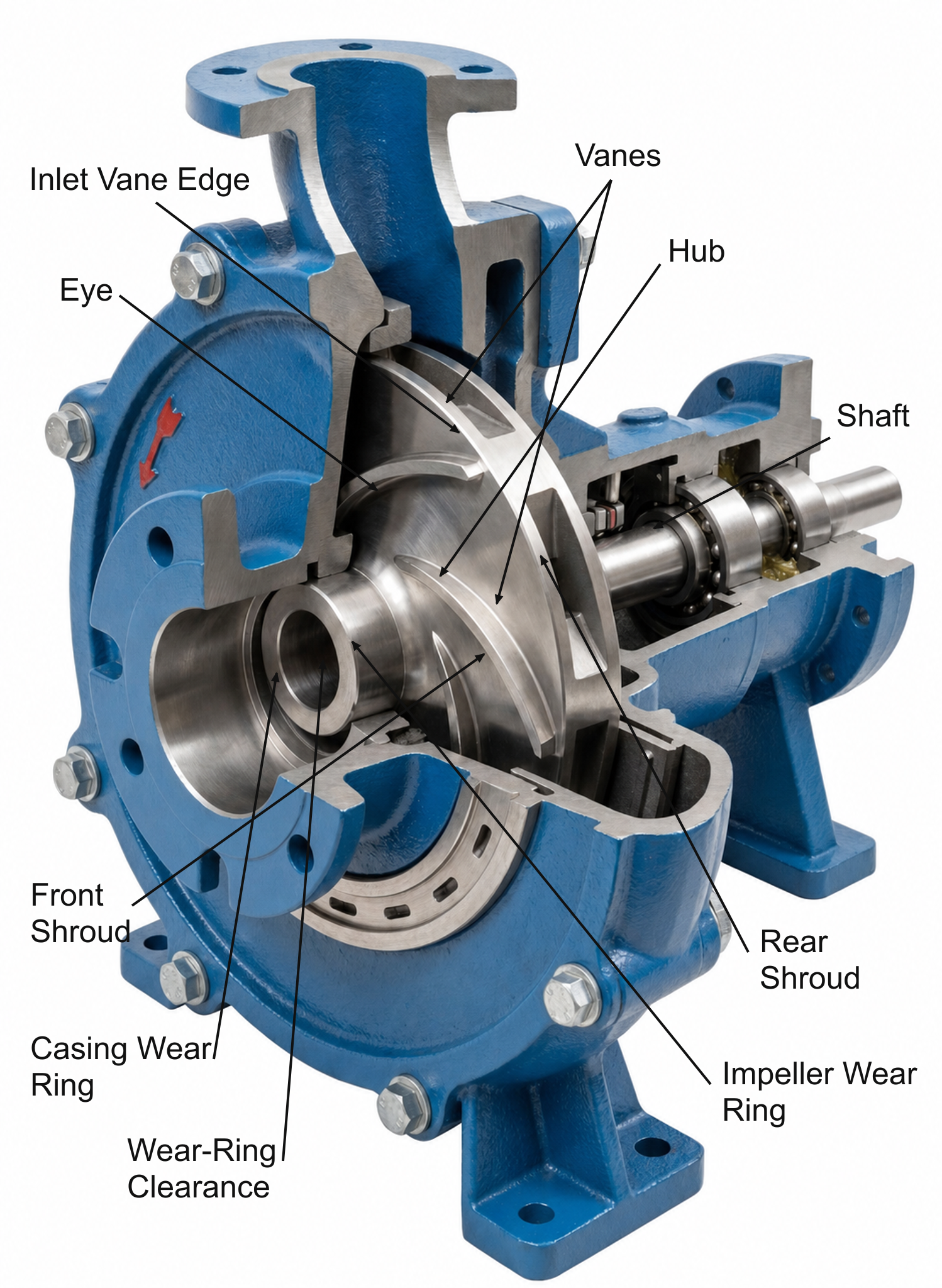
Impeller Parts: Eye, Vanes, Shrouds, Hub and Wear Surfaces
Each physical feature on an impeller serves a hydraulic or mechanical function. Knowing the parts helps you read damage, discuss wear with a vendor, and validate replacement scope.
Eye and inlet edge. The eye is the suction-side opening where liquid enters. Eye diameter influences NPSHR and inlet recirculation. A larger eye can reduce inlet velocity and NPSHR in a particular design, but an oversized eye can worsen recirculation and part-load behavior; use manufacturer curves rather than a universal rule. The inlet edge (the leading edge of each vane) is where cavitation pitting commonly starts because this is the lowest-pressure zone in the impeller. Inspect the eye and inlet edges for pitting, erosion, or polished bands during every pump teardown.
Vanes. Vanes transfer shaft work to the fluid. Vane count, inlet and outlet angles, curvature, thickness, and passage width influence the H-Q curve, efficiency, NPSHR, and solids-passing ability. Fewer, wider passages are often used to improve solids handling, while more vanes may reduce slip but can also increase blockage and friction. The net effect on head and curve shape is design-specific; do not infer head or NPSHR from vane count alone.
Shrouds. A front shroud (suction side) and rear shroud (drive side) enclose the vane passages. Closed impellers have both shrouds. Semi-open impellers have only a rear shroud. Open impellers have no front shroud and no, or only a minimal, back shroud. Shrouds control internal leakage, influence axial thrust balance, and provide wear surfaces. Rear shrouds often carry pump-out vanes that reduce pressure at the seal chamber and help exclude solids from the stuffing box area.
Hub and bore. The hub mounts the impeller to the shaft via a keyway, taper, or threaded fit. Hub fit and runout affect balance, vibration, and seal life. A worn bore can introduce runout even if the vanes and shrouds are in good condition.
Wear surfaces. On semi-open impellers, the exposed vane tips or front vane edges run close to a stationary wear plate or suction liner; there is no front shroud. On open impellers, clearances may exist on both sides depending on the design. On closed impellers, wear rings at the eye — and sometimes at the back shroud — form the primary sealing interface. As these surfaces wear, clearance opens and internal recirculation increases. Photograph these surfaces before cleaning; the wear pattern tells a story that wire-brushing erases.
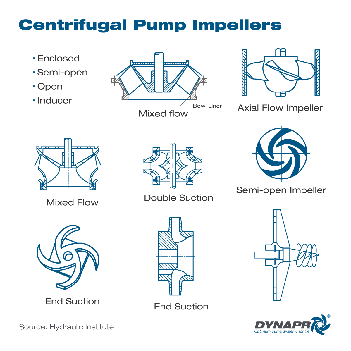
Open, Semi-Open, Closed, Recessed and Specialty Impellers
Impeller design families differ in how they handle clearance, solids, efficiency, and NPSH. Understanding the tradeoffs helps you judge whether to stay with the same family or switch designs for a changed application.
Open impellers have no front shroud and no, or only a minimal, back shroud. Their vanes operate close to one or more casing walls, side plates, or liners to control internal leakage; depending on the design, more than one running clearance may affect performance. Open impellers handle some solids, are easier to clean, and are common in smaller pumps and certain slurry designs. Their efficiency is more sensitive to clearance growth than closed designs because the leakage path is direct — from the vane pressure side straight to suction across the vane tip. When clearance opens on an open impeller, efficiency falls faster than on a closed design with comparable wear.
Semi-open impellers carry a rear shroud but no front shroud. The rear shroud adds mechanical stiffness and provides a surface for pump-out vanes. The front vane-to-casing clearance still controls leakage and efficiency. Semi-open designs are widely used in ANSI process pumps, wastewater pumps, and some slurry pumps because they balance solids tolerance with reasonable efficiency. The rear shroud changes axial-thrust and seal-chamber behavior, but thrust and allowable clearance remain design-specific and must be checked against OEM data.
Closed impellers have both front and rear shrouds, enclosing the vane passages fully. Efficiency is often higher because internal leakage is controlled at the wear ring clearances at the eye and, on some designs, at a back wear ring or balance holes. Head capability still depends on diameter, speed, vane geometry, and casing design; it is not determined by the presence of shrouds alone. Closed impellers can clog more easily with stringy solids or large debris. They are standard in clear-water, chemical, boiler-feed, and high-efficiency process services. When a closed impeller loses efficiency, measure wear ring clearance first — it is the most common degradation path.
Recessed (vortex) impellers sit back in a recessed casing cavity. They create a vortex that moves the pumped liquid without most solids passing through the vane passages. Efficiency is typically lower than that of a comparable channel or conventional impeller, but the actual value is design- and duty-specific and must come from the pump curve. The design handles large solids, rags, and sludge that could clog other impeller types. Use recessed impellers when solids passage trumps energy cost.
Specialty designs. Single-suction impellers admit liquid through one eye. Double-suction impellers admit liquid through both eyes, balancing axial thrust and enabling higher flows at a given NPSHR. Reverse-vane impellers are a distinct design in which the main pumping vanes and controlled running clearance are referenced to the rear cover; they should not be confused with auxiliary pump-out vanes used on other impellers. Their seal-chamber pressure and thrust behavior are design-specific — a topic covered in the reverse vane impeller selection guide. Non-clog impellers use wide passages and reduced vane counts for wastewater and sludge. Radial-flow, mixed-flow, and axial-flow impellers are classified primarily by flow direction and geometry, which correlate with specific speed: radial impellers generally occupy lower specific speeds, mixed-flow impellers intermediate values, and axial-flow impellers higher values.
How Diameter, Speed and Vane Geometry Shape the Pump Curve
A pump curve is not a generic rating. It belongs to a specific pump model, impeller diameter, speed, and test condition. Each impeller diameter in the same casing produces a separate curve with its own efficiency profile.
Diameter. Impeller outside diameter is the dominant variable. Larger diameter increases tip speed, which increases head and flow capacity. The Hydraulic Institute and the DOE/HI Sourcebook give the classic affinity-law approximations for small diameter changes at constant speed:
$$
\frac{Q_2}{Q_1} = \frac{D_2}{D_1}
$$
$$
\frac{H_2}{H_1} = \left(\frac{D_2}{D_1}\right)^2
$$
$$
\frac{BHP_2}{BHP_1} = \left(\frac{D_2}{D_1}\right)^3
$$
Where \(Q\) is flow (gpm), \(H\) is head (ft), \(BHP\) is brake horsepower, and \(D\) is impeller diameter (in).
⚠️Warning: Affinity laws are screening math, not proof of final performance. They are approximations for small diameter changes. Manufacturer curves and test data must control final decisions. Never use affinity scaling to justify an impeller diameter change beyond the manufacturer's published curve.
Speed. Changing pump speed shifts the curve: flow varies directly with speed, head with speed squared, and power with speed cubed. Speed changes also move NPSHR and can push the pump into a different hydraulic regime. Check the manufacturer's minimum and maximum speed limits and verify NPSHA still exceeds NPSHR at the new speed before committing.
Vane geometry. Vane count, inlet and discharge angles, passage width, thickness, and casing interaction influence curve shape. Changing vane count alters slip, blockage, friction, and hydraulic loading, but it does not produce a universal change in head or curve slope. Passage geometry affects efficiency, solids passage, and suction performance; use the manufacturer's tested curve for the complete hydraulic design.
Specific speed. Specific speed is an index that correlates flow, head, and speed with the general impeller geometry: radial designs usually occupy lower values, mixed-flow designs intermediate values, and axial-flow designs higher values. It is a useful classification parameter, not a stand-alone selection target.
For a compact power check, the DOE/HI Sourcebook fluid power formula puts the pump's hydraulic output in perspective:
$$
\text{Fluid power (hp)} = \frac{H \times Q \times SG}{3{,}960}
$$
Where \(H\) is head (ft), \(Q\) is flow (gpm), and \(SG\) is specific gravity. Compare the result to brake horsepower from the pump curve. If input power or energy per unit flow worsens, compare the duty point, clearances, fluid properties, mechanical condition, and measurement uncertainty; clearance growth is one possible cause, not a diagnosis by itself.
✓Decision Point: When the pump's actual operating point sits far from the curve prediction, check clearance, NPSH margin, and system curve before you touch the impeller diameter. An impeller trim on a pump that has opened clearances or a suction restriction will not restore performance.
How Clearance, Wear, NPSH and Off-BEP Operation Change Performance
Performance degradation in centrifugal pump impellers rarely announces itself with a sudden failure. It accumulates through clearance growth, wear, suction problems, and operation away from the design point.
Clearance and internal recirculation. Worn wear rings or opened vane-to-casing clearances create a path for liquid to recirculate from the high-pressure side back toward suction. The pump can draw similar power while delivering less useful flow. When efficiency drops, measure clearances against OEM tolerances before you assume the impeller is hydraulically wrong or the motor is failing.
BEP, POR and AOR. Every impeller has a best efficiency point — the flow and head at which pump efficiency is maximum for the stated speed and impeller diameter. ANSI/HI 9.6.3 defines the preferred operating region (POR) and allowable operating region (AOR) around BEP. Operating outside POR increases hydraulic forces, vibration, and recirculation. Seal and bearing life shorten. An impeller that looks mechanically perfect can still be the wrong hydraulic fit if the pump runs far from BEP.
NPSH and cavitation. NPSHA is a system property determined by suction conditions, liquid level, vapor pressure, and friction losses. NPSHR is a manufacturer-supplied pump characteristic: the minimum NPSH needed to achieve specified performance at a stated flow, speed, and pumped liquid. It does not mean cavitation-free operation. ANSI/HI 9.6.1 requires NPSHA to exceed NPSHR with an application-specific margin; inadequate margin can cause noise, vibration, performance degradation, cavitation damage, and reduced reliability. Vapor bubbles can form near the inlet and collapse in higher-pressure regions. Pitting concentrated near the eye is consistent with cavitation but is not diagnostic by itself; erosion, corrosion, and recirculation damage must also be considered. Read the full diagnosis in the cavitation analysis article.
Off-BEP symptoms that look like impeller problems. Low-flow operation produces suction and discharge recirculation that damage the impeller eye and vane tips. High-flow operation increases NPSHR and can pull the pump into cavitation even with adequate static suction pressure. Before you blame the impeller, verify the pump is running in POR, check NPSHA against NPSHR, and rule out a system curve that has shifted.
The table below maps the main impeller variables to what they change and what to check.
| Impeller feature or condition | What it changes | Field evidence | Deeper resource |
|---|---|---|---|
| Eye diameter | NPSHR, part-load efficiency | Cavitation noise at design flow; pitted inlet edges | Pump curves article |
| Vane count and discharge angle | Slip, losses, curve shape, solids passage | Changed curve shape or clogging risk; verify with OEM hydraulic data | Slurry impeller selection guide |
| Shroud design (open vs closed) | Efficiency ceiling, clearance sensitivity, solids passage | Efficiency drops faster on open impellers as clearance grows | Wear ring clearance article |
| Outside diameter (original or trimmed) | Flow, head, BHP per affinity laws | Changed duty point; motor load shift from curve prediction | Impeller trimming vs VFD |
| Wear ring or vane-tip clearance | Internal recirculation, volumetric efficiency | Rising kW per gallon; pump off curve with no mechanical noise | Wear ring clearance article |
| Impeller material | Wear life, corrosion resistance, chemical compatibility | Accelerated wear; pitting; coating loss; corrosion product in fluid | Slurry impeller materials article |
| Operating speed | Flow, head, power, NPSHR | Curve shift; cavitation onset at different flow than expected | Pump curves article |
| NPSH margin | Cavitation risk, reliability, impeller pitting | Noise at suction; vibration; pitted eye and inlet edges | Cavitation analysis article |
| Duty point vs BEP/POR/AOR | Hydraulic forces, vibration, seal and bearing life, energy cost | High vibration; short seal MTBF; rising bearing temperature at steady load | Pump curves article |
Match the Impeller to Fluid, Solids, Materials and Duty
Impeller selection is not a single-variable decision. The fluid, the solids load, the material, and the duty point interact. Get one wrong and the best hydraulic design fails early.
Fluid properties. Viscosity shifts the pump curve — head and flow drop while power rises. Use the Hydraulic Institute viscosity correction factors to adjust the water-performance curve. Specific gravity changes power draw directly without changing the head-flow curve when viscosity and other relevant fluid properties remain comparable. Temperature affects vapor pressure and therefore NPSHA. Corrosiveness drives material choice and can override hydraulic preference.
Solids. Particle size, shape, concentration, and hardness determine whether you need wide vane passages, a recessed design, a hard-metal material, or a different impeller family. A closed impeller that runs efficiently on clear water can clog within hours on stringy solids or rags. For slurry services, geometry and material selection must be decided together.
Duty point and operating range. An impeller selected at BEP for a steady-load pump is a different problem from an impeller that must operate across a wide flow range. If the duty cycle includes extended low-flow or high-flow operation, factor those operating points into the POR/AOR check before committing to a diameter, speed, or material. When the operating range is wide and variable, explore whether a VFD should be considered instead of trimming.
iNote: For slurry, abrasive, and corrosive services where material choice is the dominant question, the full material comparison lives in the slurry pump impeller materials article. This hub covers the general selection inputs; route material-heavy decisions there.
What to Inspect Before You Trim, Replace or Upgrade an Impeller
Before you change hardware, rule out the system. An impeller swap on a misdiagnosed problem wastes a rebuild budget and leaves the real issue running.
📋Use this checklist before you order parts or schedule the work
- ☐Confirm the actual duty point: measure flow and head with calibrated instruments.
- ☐Read the pump curve for the installed impeller diameter and speed.
- ☐Identify the current impeller diameter, material, and any previous trim from the nameplate, pump file, or direct measurement.
- ☐Verify OEM minimum and maximum trim limits. Contact the manufacturer for data. Do not trim below 75 percent of maximum impeller diameter without explicit OEM approval.
- ☐Check NPSHA vs NPSHR at the actual operating flow. Use the pump curve NPSHR line plus the HI-recommended margin.
- ☐Measure wear ring and/or vane-tip clearances. Compare to OEM tolerances — do not use a universal clearance rule.
- ☐Inspect the impeller wear pattern: inlet-edge pitting, polished recirculation bands, uneven vane wear, shroud rubs, corrosion, cracks, coating loss.
- ☐Verify material against process fluid chemistry, temperature, solids type, and pH.
- ☐Review motor load: compare measured kW or amps to the pump curve BHP prediction at the actual flow and specific gravity.
- ☐Record baseline vibration and shaft runout before disassembly. After removal or repair, verify impeller condition, runout, and balance using the applicable OEM or qualified-shop procedure.
🔴Caution: Do not trim an impeller below the manufacturer's published minimum diameter. In the absence of a published OEM limit, do not reduce it below 75 percent of maximum impeller diameter without explicit manufacturer approval; Hydraulic Institute guidance notes that excessive trimming can create hydraulic instability and performance problems.
💡Tip: Photograph the impeller from both sides, the volute cutwater, and the wear rings before you clean anything. Those images preserve the wear pattern evidence that disappears once the parts are wire-brushed or blasted. Send them with your parts inquiry — they often answer the material and geometry questions before the first phone call.
If after going through this checklist the pump still cannot meet the curve with acceptable clearance and healthy NPSH margin, do not guess. Send the pump model, curve, current impeller diameter and material, duty point, clearance measurements, wear photos, and operating symptoms to an applications engineer.
Send Dynapro your pump model, curve, current impeller diameter and material, duty point, and NPSH data if available. Include wear photos and clearance measurements. Our team will review whether the right next step is replacement, trim, material change, or a different hydraulic design. Contact Dynapro Engineering Support
Deeper Dynapro Resources for the Next Decision
This article is the engineering map. The articles below go deeper on specific decisions. Use this table to route yourself to the right next resource.
| When you need to... | Read this article |
|---|---|
| Read and interpret pump curves before changing impeller diameter or speed | Pump Curves 101: Interpret Performance Charts |
| Understand wear ring clearance, internal recirculation, and efficiency loss in closed impellers | Pump Wear Rings: Clearance and Efficiency |
| Select a slurry pump impeller for solids, abrasion, and specific wear patterns | Slurry Pump Impeller Selection |
| Compare impeller materials: high chrome, rubber, polyurethane, ceramic, and coated-metal options | Slurry Pump Impeller Materials |
| Diagnose cavitation pitting at the impeller eye and correct NPSH margin | Cavitating Pump Analysis: Engineering Techniques |
| Decide between impeller trimming and a VFD for oversize correction | Impeller Trimming vs VFD |
| Understand reverse-vane impeller operation, seal chamber benefits, and application fit | Reverse Vane Impeller Selection Guide |
FAQs
What does a centrifugal pump impeller do?
It transfers shaft energy to the liquid, increasing both velocity and static pressure through the vane passages. The casing then converts part of the remaining velocity into additional static pressure. The impeller sets the pump's H-Q curve, NPSHR, efficiency, solids-handling ability, and thrust characteristics.
What are the main types of centrifugal pump impellers?
The main families are open (no front shroud and no or minimal back shroud), semi-open (rear shroud only), closed (front and rear shrouds), and recessed/vortex (impeller sits back in a casing cavity). Each type trades efficiency, solids tolerance, clearance sensitivity, and clogging resistance differently.
How does impeller diameter affect flow and head?
Larger diameter increases tip speed, which raises head and flow capacity. The affinity laws approximate that flow varies with diameter, head with diameter squared, and power with diameter cubed — but these are screening estimates. Always confirm with the manufacturer's pump curve.
What happens when impeller clearance opens up?
Internal recirculation increases. Liquid leaks from the high-pressure side back toward suction through the wear ring or vane-tip gap. The pump can draw similar power while delivering less useful flow to the system. Efficiency drops before the pump looks mechanically broken.
When should an impeller be trimmed instead of replaced?
When the pump is oversized for the actual duty point and the required diameter reduction falls within the OEM's published trim range and above 75 percent of maximum diameter. Trimming permanently reduces flow, head, and power. A VFD may be a better option when the duty varies or when trimming would push the impeller into an unstable hydraulic region. Contact the manufacturer for trim data before cutting metal.
How do I choose impeller material for abrasive or corrosive service?
Match the material to the dominant wear mechanism — abrasion, erosion, corrosion, or combined erosion-corrosion — considering particle size, hardness, concentration, fluid chemistry, pH, and temperature. High-chrome iron, rubber, polyurethane, ceramic inserts, and coated-metal systems each suit different conditions. This topic requires its own dedicated selection process; see the slurry pump impeller materials article for the full comparison.
References
- Hydraulic Institute, ANSI/HI 14.1-14.2 Rotodynamic Pumps for Nomenclature and Definitions: https://www.pumps.org/product/ansi-hi-14-1-14-2-rotodynamic-pumps-for-nomenclature-and-definitions/ (paywalled)
- Hydraulic Institute, ANSI/HI 14.3 Rotodynamic Pumps for Design and Application: https://www.pumps.org/product/ansi-hi-14-3-rotodynamic-pumps-for-design-and-application-2/ (paywalled)
- Hydraulic Institute, ANSI/HI 9.6.3 Rotodynamic Pumps — Guideline for Operating Regions: https://www.pumps.org/product/ansi-hi-9-6-3-rotodynamic-pumps-guideline-for-operating-regions/ (paywalled)
- Hydraulic Institute, ANSI/HI 9.6.1 Rotodynamic Pumps — Guideline for NPSH Margin: https://www.pumps.org/product/ansi-hi-9-6-1-rotodynamic-pumps-guideline-for-npsh-margin/ (paywalled)
- Hydraulic Institute, ANSI/HI 14.6 Rotodynamic Pumps for Hydraulic Performance Acceptance Tests: https://www.pumps.org/product/ansi-hi-14-6-rotodynamic-pumps-for-hydraulic-performance-acceptance-tests/ (paywalled)
- U.S. Department of Energy / Hydraulic Institute, Improving Pumping System Performance: A Sourcebook for Industry: https://energy.gov/sites/prod/files/2014/05/f16/pump.pdf
- Hydraulic Institute, Trimming Impellers to Reduce Energy Consumption: https://www.pumps.org/2022/09/27/trimming-impellers-to-reduce-energy-consumption/


