

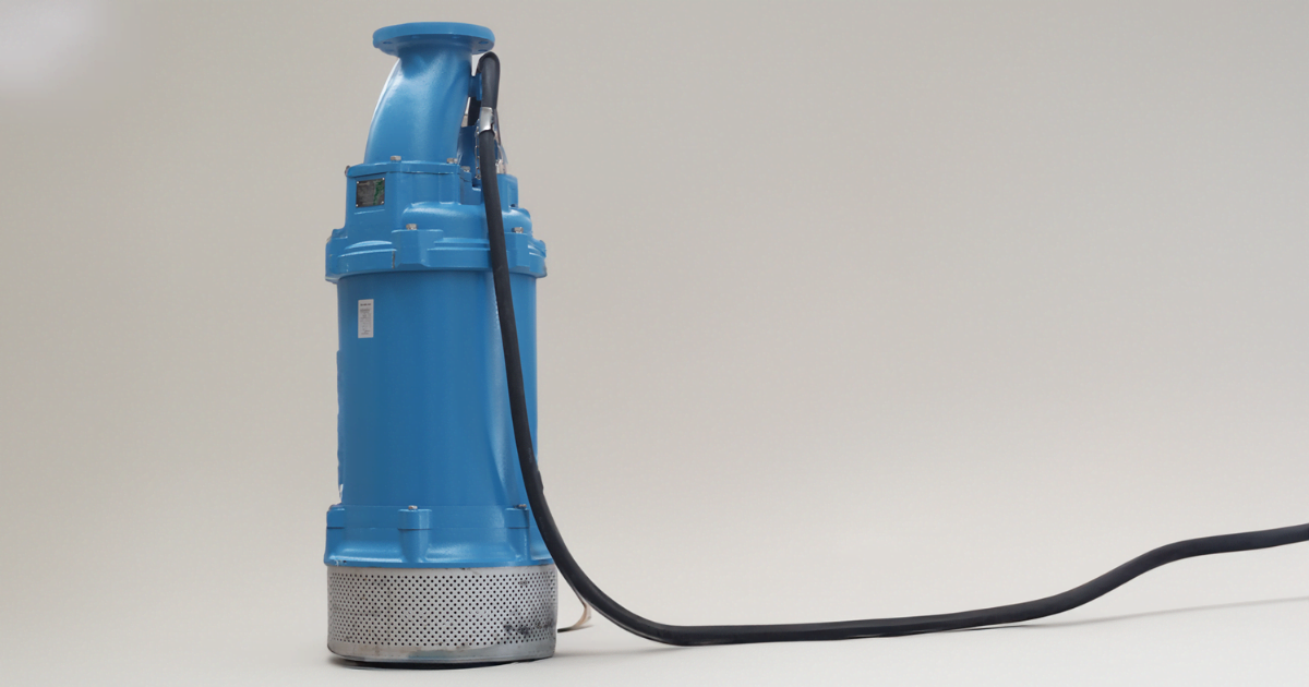
A submersible pump is a pump-and-motor assembly designed to run submerged in the fluid it moves. The term describes an installation configuration, not one hydraulic principle.
The label is where the confusion starts. A borehole water pump, a wastewater unit and a construction dewatering pump are all submersible, yet they share almost nothing at selection level: different hydraulics, solids capability, cooling, materials and controls.
This guide walks you through five decision layers: hydraulic principle, construction, installation, application and duty. You will see how a submersible pump converts motor input into flow and head, which components carry the load, how the main configurations differ, and which inputs drive selection. Deep maintenance, model-specific troubleshooting, detailed sizing and purchasing stay with their dedicated resources; here you build the mental model and learn where to route each next question.
Key Terms
– Duty point: The flow and head where the pump curve and the system curve intersect.
– System curve: The head the piping requires as a function of flow: static lift, elevation and friction losses.
– Total system head (TDH): The total energy per unit weight the pump must add: static head plus pressure differences plus dynamic losses.
– BEP (Best Efficiency Point): The flow at which the hydraulic design runs at its highest efficiency for a given speed and impeller diameter.
– NPSHA / NPSHR: Net positive suction head available, a system property, versus required, a pump property; available must exceed required with an application-appropriate margin.
– Solids passage: A model-specific indication of the particle dimension or passage geometry the wet end is designed to accommodate. It does not by itself guarantee performance with a given solids concentration, shape or abrasiveness.
– Continuous / intermittent duty: Whether the design allows sustained running or needs rest periods; rated per model and service.
What Is a Submersible Pump?
A submersible pump is a pump whose motor and wet end form one close-coupled assembly intended to operate submerged in the pumped fluid. The defining feature is the configuration, not the hydraulic principle inside. In most industrial services that principle is rotodynamic: an impeller adds energy to the fluid, and a diffuser or volute converts that energy into pressure. The submerged arrangement is what changes everything else around that principle.
Keep five decision layers separate when you classify one of these machines:
| Decision layer | Question to answer | What the answer controls |
|---|---|---|
| Hydraulic principle | How does the pump add energy to the fluid? | Curve shape, flow-head behavior and fitting service range |
| Construction | Single or multistage? Diffuser or volute? Which impeller geometry and materials? | Head per stage, solids passage, wear life, sealing system |
| Installation | Borehole, guide-rail wet well or portable sump mounting? | Intake conditions, cooling path, removal method, access |
| Application and fluid | Clean water, wastewater, dewatering with fines or process fluid? | Impeller geometry, wetted materials, sealing requirements |
| Duty and environment | Continuous or intermittent? Which power, controls and area classification? | Motor rating, protection scheme, control strategy |
The same label can therefore require different curves, solids passage, materials, controls, removal methods and maintenance plans.
iNote: Submersible is a configuration, not one hydraulic family. A borehole water pump, a wastewater pump and a construction dewatering pump may share the label and almost nothing else at selection level. Classify by principle, construction, installation, application and duty before comparing models.
How a Submersible Pump Works
With the map in place, follow the energy path from the power cable to the discharge:
- Power enters through a sealed cable and drives the submerged motor.
- The motor turns the shaft, and the impeller accelerates the fluid.
- The diffuser or volute converts velocity into pressure.
- The discharge path, a column in a borehole or an elbow and riser in a wet well, carries the flow into the system.
What leaves the discharge is flow delivered against head.
Because the assembly sits in the fluid, the intake is already submerged and the pump starts from the pressure available at its intake. The submerged intake reduces some external priming and suction-lift complications, but it does not by itself establish the separate self-priming capability defined for other pump arrangements. That distinction returns in the common misunderstandings section.
How much head reaches the system depends on where the pump runs on its curve. The pump curve shows the head the pump can add at each flow; the system curve shows the head the piping requires at each flow. Their intersection is the duty point, and that point, not the motor rating, defines what the unit delivers. Deep-well designs stack several impeller and diffuser stages on one shaft, and each stage adds a portion of the total head.
One more energy path matters: heat. The motor rejects heat to the surrounding fluid, and some designs use an internal cooling jacket or oil fill; the minimum flow and submergence that keep that path working are model-specific.
Main Components and What They Control
The path holds together through a specific set of parts. Group them into the wet end, the motor and sealing system, and the discharge path. The table gives each one's job, what commonly fails when it stops doing that job, and what to verify.
| Component or subsystem | What it controls | Typical consequence when it fails | Verify before selection or action |
|---|---|---|---|
| Motor and enclosure | Converts electrical input into shaft torque; duty and enclosure ratings set run time and location | Winding damage from moisture ingress or overheating | Voltage, phase, frequency, cooling method, protection |
| Power cable and cable entry | Carries power across the submerged boundary | Insulation failure, moisture ingress into the motor | Cable length, jacket, entry design |
| Impeller | Adds energy to the fluid; geometry sets solids passage and head per stage | Wear, erosion, clogging or recirculation losses | Hydraulic type, curve, passage geometry |
| Diffuser or volute casing | Converts velocity into pressure and guides flow to discharge | Recirculation, efficiency loss, erosion | Construction, stages, clearances |
| Shaft, bearings and thrust system | Transmit torque and hold the rotor in position | Deflection, fatigue, vibration, contact damage | Load basis, orientation, OEM lubrication |
| Mechanical seals | Exclude fluid from the motor along the shaft | Leakage into the motor, motor failure | Seal arrangement, face and elastomer compatibility |
| Intake screen or strainer | Keeps large debris out of the wet end | Clogging, low flow, poor suction | Submergence, approach flow, solids |
| Sensors and controls | Detect level or equipment conditions and command operation | Dry-run exposure, short cycling, overload | Sensor type, alarm logic, setpoints |
| Guide rail, lifting points or suspension | Position and retrieve the unit | Cable or casing damage from a bad lift | Permitted lifting method, loads |
| Discharge connection and check valve | Directs flow into the system; check valve behavior is system-dependent | Backflow or water hammer where the system needed prevention | Piping layout, rising-main design |
🔴Caution: Never lift a submersible pump by its power cable. Use the lifting points and method defined in the selected model's IOM.
Submersible Pump Types and Configurations
Those component choices cluster into recognizable configurations. The Hydraulic Institute defines submersible rotodynamic types in its pump-type references: OH8, an overhung impeller, close-coupled, submersible, single-stage pump; OH8b, its volute variant; and VS0, a vertically suspended pump discharging through a column. Those names describe hydraulic construction. For selection, organize by installation and service instead.
Borehole and deep-well pumps
Slim, often multistage units that discharge through a column inside the well casing. They are commonly used where a narrow installation must develop substantial head, but the actual service range depends on the model. Bore diameter, water quality, sand content, thrust handling, NPSH margin and cooling flow all require verification against the manufacturer's curve and IOM.
Dewatering and construction pumps
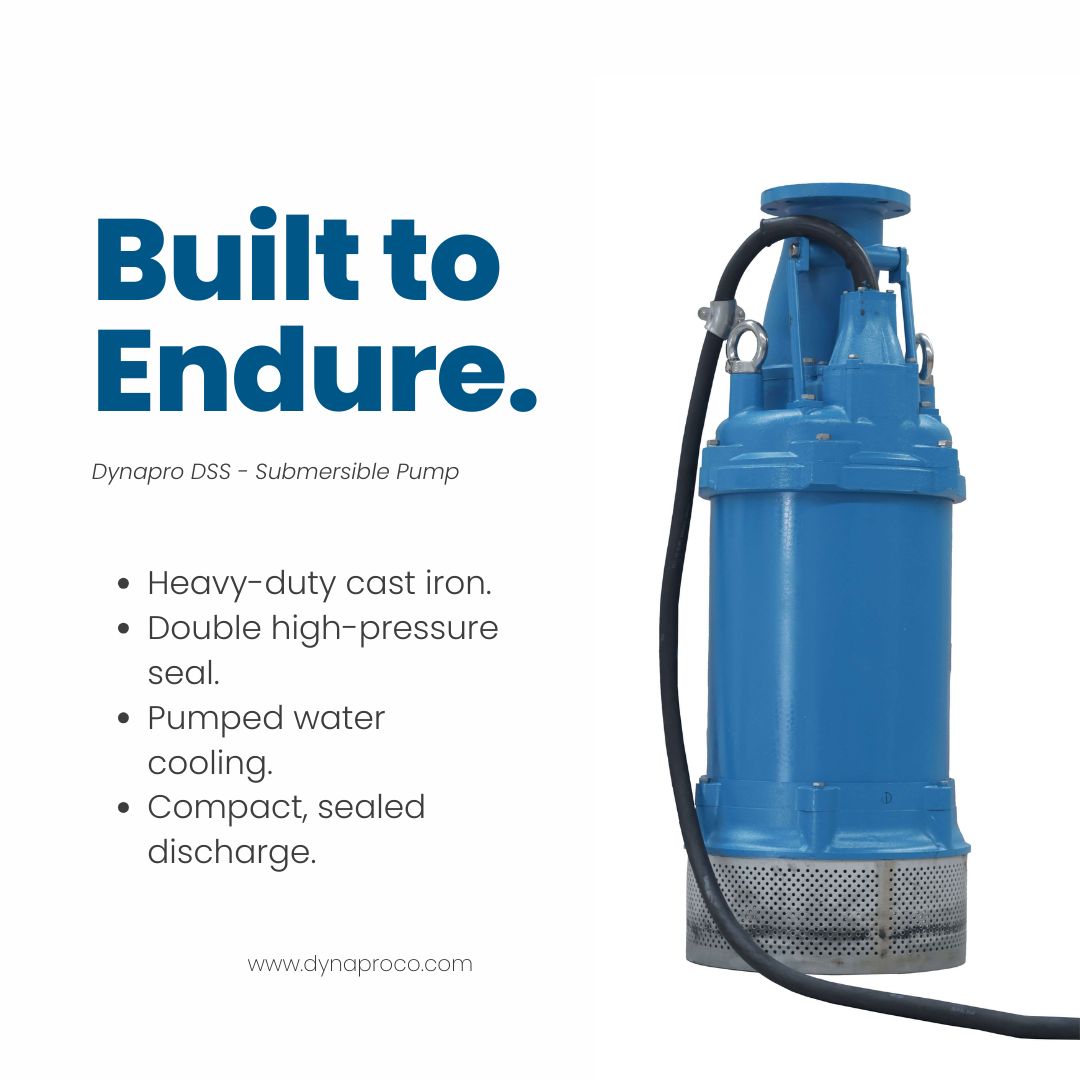
Portable or fixed units used in sumps, excavations and temporary drainage duties. Depending on the design, they may incorporate wet ends and materials intended for fines, sediment or abrasive solids. Confirm the expected water level, sediment load, solids passage, hose or piping losses, cooling requirements and retrieval method; the dewatering label alone does not establish hydraulic range, wear resistance or dry-run capability.
Wastewater and sewage pumps
Wet-well units with non-clog, channel or vortex impellers sized to pass rags and solids. They work with level controls, intermittent starts and corrosive gas environments, so materials and motor duty matter as much as the hydraulics. Confirm the actual free passage and operating region from the manufacturer.
Industrial process pumps
Any of the above constructions with wetted materials, sealing and motor ratings matched to a specific process fluid, temperature or hazardous area. Here the fluid property list, not the configuration family, leads the specification.
Where these configurations fit among the broader industrial pump families is a taxonomy question of its own; the full map sits in the companion article on pump families across industry.
Industrial Applications and Operating Limits
Configurations exist because applications differ, and each application imposes its own limits. The three scenarios below are hypothetical illustrations of different input sets, not descriptions of installed equipment.
- Hypothetical mine sump dewatering. Abrasive fines, changing lift, peak inflow; the pump may run through a full shift. Hard questions: solids passage, wear materials, cooling at minimum level and starts per hour.
- Hypothetical wastewater wet well. Rags and fibers, variable inflow, intermittent starts, corrosive gas. Hard questions: non-clog geometry, level controls, wetted materials and motor duty.
- Hypothetical deep-well supply. Clean water at high head inside a narrow casing. Hard questions: multistage head, bore diameter, thrust capacity and NPSH margin at low water level.
Each scenario points at a different configuration, and the answers live in the selected model's curve and IOM. There is no universal submersible value for depth, temperature, solids passage, submergence or runtime. A number quoted without a model behind it is a number to reject.
Hazardous locations require the pump, cable system, controls and installation to match the area classification and local electrical requirements; a general submersible rating does not establish compliance. Accessibility shapes maintenance too: retrieval equipment, isolation and confined-space controls are easier to plan before installation than after a failure.
⚠️Warning: Verify the model limit. Depth, minimum submergence, solids passage, temperature, duty cycle, cable and material limits all come from the selected model's curve and IOM. A value valid for one configuration does not transfer to another.
Selection Inputs: Flow, Head, Fluid, Solids and Duty
Turn those application limits into inputs. Select the pump from the system, not from horsepower. The five inputs that matter most are flow, head, fluid, solids and duty, plus the installation and electrical environment around them.
Flow and total system head
Record minimum, normal and maximum flow, including seasonal levels and inflow peaks. A single design flow hides the hours the pump spends at lower demand. For level-controlled sumps, record the usable volume and the expected inflow pattern: both set starts per hour, a motor-life input.
Then build the total system head: static lift and elevation, pressure required at the destination, and the dynamic losses through piping, valves and fittings. In turbulent flow those dynamic losses scale approximately with the square of flow rate, so doubling flow through the same line roughly quadruples its friction loss.
The duty point is where the pump curve and the system curve intersect. Plot the system requirement across the expected flow range, and choose a pump whose operating range covers it. Horsepower is a consequence of the duty point; it never defines it.
Fluid properties and solids
Density, or specific gravity, affects the power required. Viscosity shifts centrifugal performance and suction-side losses. Temperature affects materials and vapor pressure. Chemistry drives the wetted material choice, from cast iron to stainless or higher alloys. Dissolved or entrained gas changes intake behavior.
Solids set the wet end. Size, concentration, hardness and abrasiveness decide between closed, open, non-clog and vortex impellers, and between standard and wear-resistant materials. In wastewater service, rags and fibrous material set passage geometry. The solids passage rating is a design value, not an attitude. How solids and slurry properties change pump requirements is worth its own pass when your fluid stops being clean water.
Suction conditions and NPSH
Submersion usually improves the pressure available at the intake, but it does not remove the check. NPSHA is a property of your system; NPSHR is a property of the pump. The available value must exceed the required value with an application-appropriate margin under ANSI/HI 9.6.1, and there is no universal percentage to paste onto that margin.
Installation, power and environment
Record the sump or well geometry, the minimum submergence, and how the unit will be lifted out, whether by guide rails or lifting chain. Confirm voltage, phase and frequency, plus cable distance and the starting method. Record the hazardous area classification. Decide the controls before quoting: level control, thermal and dry-run protection, and whatever monitoring the site standard expects.
Minimum data to gather before model selection
- Flow rate and its expected range: minimum, normal and maximum.
- Total system head at those flows: static lift, pressure requirement and friction losses.
- Fluid: density, viscosity, temperature, chemistry, corrosivity and gas content.
- Solids: maximum particle size, concentration, hardness and abrasiveness.
- NPSHA at the intake, to compare against candidate NPSHR with margin.
- Installation: sump or well dimensions, submergence and removal method.
- Piping: sizes, lengths, fittings, valves and discharge conditions.
- Duty: continuous or intermittent, run duration, starts per hour and redundancy.
- Power: voltage, phase, frequency, cable distance and available capacity.
- Environment: hazardous area classification and ambient conditions.
- Controls: level control, dry-run and thermal protection, monitoring.
- Materials, lifting and maintenance constraints.
Application and Selection Matrix
With those inputs in hand, the matrix turns them into a first pass. It gives conditional guidance at configuration level, never a model recommendation. Every limit cell is a verify cell.
| Application | Fluid and solids | Flow and head pattern | Installation | Duty and environment | Configuration cue | Limit to verify | Next source |
|---|---|---|---|---|---|---|---|
| Mine sump dewatering | Abrasive fines, particle size and concentration | Changing lift, hose or pipe losses, peak inflow | Portable or fixed sump mounting | Intermittent to continuous, abrasive | Wear-resistant dewatering unit | Solids passage, wear life, minimum submergence, motor load | Curve, IOM and site solids data |
| Construction excavation dewatering | Sediment, debris, entrained air | Required drawdown, changing level, temporary discharge route | Portable unit with practical retrieval | Intermittent, variable water | Portable drainage or dewatering unit | Dry-run tolerance, intake blockage, hose losses, starts | Curve, IOM and temporary works plan |
| Wastewater wet well | Rags, fibers, solids, corrosive constituents | Average and peak inflow, storage volume, force-main losses | Guide-rail wet well with level control | Intermittent starts, corrosive gas | Non-clog, channel or vortex wastewater unit | Passage geometry, operating region, minimum level, area rating | System curve, IOM and wastewater data |
| Deep-well or borehole supply | Clean water, possible sand content | Low to moderate flow, high head, rising-main losses | Slim casing, discharge through column | Continuous or long runs | Multistage borehole unit | Bore diameter, thrust, NPSH margin, cooling flow | Well data, curve, dimensional drawing and IOM |
| Industrial process sump | Chemistry, viscosity, temperature, gas and solids | Per process requirement, vessel pressure | Pit, sump or process vessel, possibly hazardous area | Continuous, possibly hot or corrosive | Process-rated unit with matched materials | Material compatibility, temperature, enclosure class | Process datasheet, curve, IOM and certifications |
If two configuration families could serve the duty, resolve it with the manufacturer curve, not with preference. The matrix narrows the field; the curve and the IOM make the call.
Efficiency and Reliability at the System Level
One filter remains before you choose: how the system will actually run the unit. Efficiency is a property of the operating point, not of the word submersible. A pump curve shows efficiency peaking at BEP and falling away on both sides. A duty point far from BEP, whether at very low flow with internal recirculation or far out on the curve, costs energy and often adds vibration or wear risk. Select a pump whose expected operating points remain within the manufacturer's preferred and allowable operating regions. Evaluate proximity to BEP as one design-specific factor, not as a universal acceptance rule.
The system usually matters more than the component. Static lift, friction losses, valve positions and control strategy set the real energy bill, and friction losses rise with roughly the square of flow. This is the DOE systems view: pumping system assessment starts with the system and its operating pattern, not with swapping a nameplate. Claims about energy savings only mean something when they are tied to a measured operating point.
Controls complete the picture. Properly designed and configured level control can reduce exposure to dry running and unnecessary cycling, but it does not replace the model's minimum-level requirements or dedicated dry-run, thermal or motor protection. A variable frequency drive helps where flow demand moves over a wide range, though a VFD does not remove static head, solids constraints, minimum speed or cooling needs. Reliability follows the same logic as efficiency: it comes from the operating point, the duty cycle, the fluid and the maintenance plan. A solids-handling unit run dry, at low submergence or outside its preferred operating region degrades regardless of its label.
The full system-level process, from requirements through fluid properties to energy-conscious decisions, is covered in the companion article on pump selection for reducing energy consumption.
Common Misunderstandings About Submersible Pumps
The label also carries shortcuts that survive because they sound right. Each one costs money when believed:
- "Submersible means self-priming." The submerged intake removes the need to prime this configuration, but self-priming is a separate capability defined for pumps that can evacuate air from a dry suction line. A submerged intake therefore does not prove a separate self-priming capability.
- "Every submersible pump handles solids." Many handle clean water only. Solids passage is set by impeller geometry and clearances, and it is always a rated value for the specific model.
- "Submerged means no cavitation." Submersion raises the pressure available at the intake, but it does not remove fluid vapor pressure, temperature, intake losses or vortexing. The NPSHA-versus-NPSHR margin still governs.
- "Submerged means it cannot overheat." Cooling depends on the motor's cooling path, flow and minimum submergence. Dry running or low-level operation can damage seals and windings as it would anywhere.
- "Horsepower alone selects the pump." The duty point sets flow and head. Fluid, solids, duty and environment set everything else. Horsepower is the result of a correct selection, not the input to one.
- "Maintenance intervals are universal." Intervals follow service severity and the OEM schedule. A rag-loaded wet well and a clean-water borehole do not share a calendar.
Where to Go Deeper
This hub explains the map. The deeper questions each have a home:
- Pump taxonomy. For where submersible configurations sit among all industrial pump families, go to the guide on pumps in industry.
- System selection and energy. For the full requirements, fluid-properties and life-cycle selection process, continue with pump selection considerations for energy consumption.
- Solids and slurries. For how solids behavior changes pump requirements, read Understanding Slurry.
- Maintenance. The dedicated English submersible maintenance guide is a planned resource in this cluster, not yet a live page. Until it exists, model-specific maintenance belongs to the OEM IOM.
Keep standards in their scope. ANSI/HI 11.6 covers mechanical and electrical integrity testing and contractual acceptance for rotodynamic submersible pumps; hydraulic performance acceptance testing sits under ANSI/HI 14.6. That is a contractual test standard, not a field maintenance checklist.
✓Decision Point: Route to procedure. Model-specific installation, maintenance and troubleshooting belong in the dedicated maintenance resource and the OEM IOM. This hub covers the map; it does not replace the procedure.
FAQs
What is a submersible pump?
A submersible pump is a pump-and-motor assembly designed to operate submerged in the fluid it moves. The term defines the installation configuration, not the hydraulic principle, which is rotodynamic in most industrial services.
How does a submersible pump work?
The motor converts electrical input into shaft torque, the impeller adds kinetic energy to the fluid, and the diffuser or volute converts that velocity into pressure. Because the intake is submerged, the arrangement reduces some external priming and suction-lift constraints, but the pump must still overcome the total system head.
Can every submersible pump handle solids?
No. Many models are built for clean water only. Solids passage is a rated value set by impeller geometry and clearances, so check the model curve and IOM before using a unit in dirty service.
Can a submersible pump run dry?
Only where the manufacturer explicitly permits it. Many designs rely on the handled fluid for cooling and seal lubrication, so confirm the minimum liquid level and any permitted dry-run window in the IOM, and protect the unit with level or dry-run protection.
What data do I need to size a submersible pump?
The checklist in the selection section collects them: flow and its range, total system head, fluid properties, solids, installation geometry, duty, power supply, environment and controls.
How often does a submersible pump need maintenance?
There is no universal interval. Frequency follows service severity, fluid and duty, and the OEM schedule for the model. Inspections of seals, cable entry and wear parts matter more in abrasive or rag-loaded service than in clean-water duty.
References
- U.S. Department of Energy, Improving Pumping System Performance: A Sourcebook for Industry, 2nd ed., 2006: https://www1.eere.energy.gov/manufacturing/tech_assistance/pdfs/pump.pdf
- Hydraulic Institute, Pump System Fundamentals New Industry Professionals Should Know, 2022: https://www.pumps.org/2022/10/03/pump-system-fundamentals-new-industry-professionals-should-know/
- Hydraulic Institute, Pump Types, HI Data Tool: https://datatool.pumps.org/introduction-definitions-references/pump-types
- Hydraulic Institute, ANSI/HI Pump Standards Inventory: https://www.pumps.org/what-we-do/standards/
- Hydraulic Institute, ANSI/HI 11.6-2022 Rotodynamic Submersible Pumps for Mechanical and Electrical Acceptance Tests: https://www.pumps.org/product/ansi-hi-11-6-rotodynamic-submersible-pumps-for-mechanical-and-electrical-acceptance-tests/ (paywalled)
- Hydraulic Institute, ANSI/HI 9.6.1-2024 Rotodynamic Pumps Guideline for NPSH Margin: https://www.pumps.org/product/ansi-hi-9-6-1-rotodynamic-pumps-guideline-for-npsh-margin/ (paywalled)


