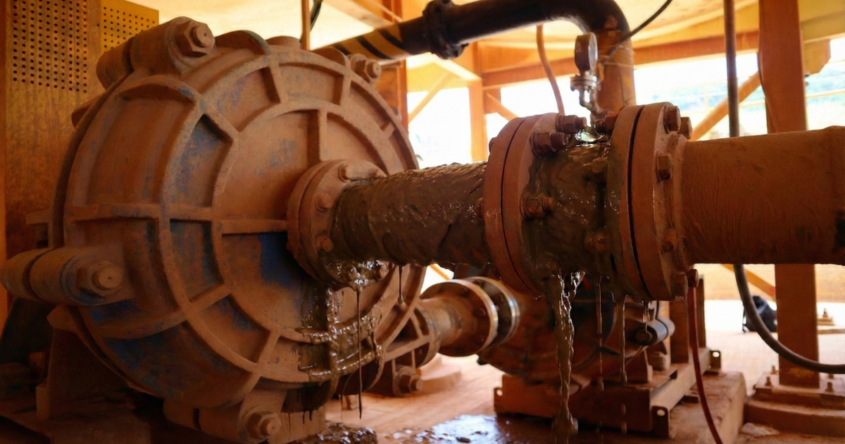
If you select or troubleshoot a centrifugal pump on a water curve and then run it on a viscous liquid, you can miss duty, trip the motor, and create avoidable downtime.
60-Second Summary (For Maintenance & Operations)
- Water curves are not "wrong"; they are just not your fluid.
- Viscosity typically reduces flow/head, collapses efficiency, and can push absorbed power into overload.
- The only defensible way to predict performance (within limits) is to correct the water curve using ANSI/HI 9.6.7, point-by-point.
- Treat the result as a gated decision: corrected duty + motor margin + NPSH margin + field validation plan.

What You Will Have When You Finish
- A corrected pump curve package for the actual fluid temperature/viscosity (within ANSI/HI method limits)
- A documented motor-load check against nameplate and site overload policy
- An NPSH margin check tied to site criteria
- A keep / trim / slow down (VFD) / re-select decision record you can defend in a review
- A startup validation checklist to prove the model in the first week.
Why Water Curves Fail in Viscous Service
What changes when viscosity increases (Newtonian liquids, within method limits)
- Flow tends to drop at the same speed/impeller.
- Head tends to drop.
- Efficiency drops (often the biggest penalty).
- Absorbed power must be re-checked because efficiency and duty point move.
Why it matters (field failures you actually see)
- Motor overload or nuisance trips after startup or after temperature shifts
- Chronic off-BEP operation: rising vibration, shorter seal/bearing life, heat rise trends
- Process under-delivery: unstable production, rework, missed targets
A simple anchor for power risk is:
Hydraulic power:
$$P_h = \rho g Q H$$
Note: In this form, use Q in m³/s. If you’re working in m³/h, use the practical power equation with the 367 constant (SI) to avoid unit errors.
Absorbed/shaft power:
$$P_{abs} = \frac{P_h}{\eta}$$
If viscosity pushes \(\eta\) down and moves \(Q\) and \(H\), your motor margin can evaporate even when the water curve looked safe.
Data Collection (Build a One-Page Input Sheet)
Most bad decisions in viscous service come from weak inputs, not weak math. Lock an auditable input package before you touch correction charts.

Fluid (at actual operating temperature)
- Operating temperature (and expected cold-start and hot-running temperatures)
- Kinematic viscosity \(\nu\) [cSt] at temperature (or dynamic viscosity \(\mu\) [cP] plus SG)
- Specific gravity \(SG\) (or density \(\rho\))
- Fluid behavior: Newtonian vs. "requires verification" (stop condition if non-Newtonian)
Unit sanity check:
$$\nu\ [\text{cSt}] = \frac{\mu\ [\text{cP}]}{SG}$$
Pump (OEM water curve)
- OEM water performance curve revision ID/date (do not use a generic family curve)
- Speed \(N\) and impeller diameter \(D\) for that curve
- Allowable operating range / minimum continuous stable flow guidance (if provided)
- OEM NPSHr curve basis (test speed/impeller)
Driver & limits (site-controlled)
- Motor rated power (kW or hp), service factor, trip settings
- Any site "continuous overload" policy (document it; do not assume)
- VFD min/max speed, torque limits (if applicable)
System
- Static head and friction model (system curve inputs). Cross-check assumptions with matching pumps to system requirements and pump energy efficiency quick diagnostics.
- Suction conditions updated for the real fluid (level, vapor pressure, suction losses)
- Duty envelope (min/normal/max Q and H)
⚠️ Field warning: if viscosity varies with temperature, do not run a single-case correction. Run cold/normal/hot sensitivity and treat any decision flip as a redesign trigger.

The Stop/Go Workflow (ANSI/HI 9.6.7)
This is a standards-first workflow. It is designed to be auditable, repeatable, and defensible.
Pre-calculation checklist (do this before charts)
- OEM water curve revision confirmed (model, speed, impeller diameter).
- Viscosity confirmed at operating temperature; cold-start and hot-running cases defined.
- Newtonian assumption stated (or flagged as "requires verification").
- Units locked (SI or USCS); conversions verified.
- System curve inputs reviewed (static + friction + control valve behavior).
- Motor/VFD limits captured; site overload policy documented (do not assume).
- NPSHa recalculated for actual suction conditions and temperature.
Gate 0: Applicability (Stop/Go)
Stop if any of these are true:
- Fluid is non-Newtonian (or unknown)
- You are outside ANSI/HI chart limits and would need extrapolation
- You do not have the correct OEM curve revision for the installed hydraulic
Gate 1: Baseline points (water curve)
Pick baseline points across the curve (at minimum: low, near BEP, and high within allowable range) and record:
\(Q_w\), \(H_w\), \(\eta_w\) at each point
Gate 2: Correction factors (ANSI/HI charts)
From ANSI/HI 9.6.7, obtain point-by-point correction factors (do not apply a single factor to the whole curve):
\(C_Q\), \(C_H\), \(C_\eta\)
Gate 3: Correct the curve (point-by-point)
Compute corrected points:
- \(Q_v = C_Q \cdot Q_w\)
- \(H_v = C_H \cdot H_w\)
- \(\eta_v = C_\eta \cdot \eta_w\)
Gate 4: Motor-load check
Compute absorbed/shaft power at corrected points and compare against motor capability and site policy.
Common power formulas:
- SI (approx.): \(P\_shaft[\text{kW}] = (Q[\text{m}^3/\text{h}] \cdot H[\text{m}] \cdot SG) / (367 \cdot \eta)\)
- USCS (approx.): \(P\_shaft[\text{hp}] = (Q[\text{gpm}] \cdot H[\text{ft}] \cdot SG) / (3960 \cdot \eta)\)
Gate 5: System overlay (find the real operating point)
Overlay the corrected pump curve and the system curve. The intersection is your predicted operating point, not the water-curve catalog point.
Gate 6: NPSH margin check
Verify \(NPSHa\) at corrected duty and compare to the OEM \(NPSHr\) basis. Confirm your site margin criterion (document it).
Gate 7: Decision + uncertainty log
Document:
- What input(s) would change the decision (viscosity vs temperature, curve revision, suction losses)
- What you will measure at startup to validate the model
- When to escalate to OEM/engineering
Worked Example (Assumed Illustrative)
This example shows mechanics only. The correction factors below are ASSUMED for demonstration; do not reuse them.
Assumed inputs (example only)
| Item | Symbol | Value | Units | Notes |
|---|---|---|---|---|
| Water-curve flow (near duty) | \(Q_w\) | 300 | $$\text{m}^3/\text{h}$$ | From OEM curve revision |
| Water-curve head (near duty) | \(H_w\) | 55 | $$\text{m}$$ | From OEM curve revision |
| Water-curve efficiency | \(\eta_w\) | 0.78 | $$-$$ | Decimal |
| Specific gravity | \(SG\) | 1.05 | $$-$$ | At pumping temperature |
| Flow correction factor | \(C_Q\) | 0.92 | $$-$$ | ASSUMED (get from ANSI/HI charts) |
| Head correction factor | \(C_H\) | 0.95 | $$-$$ | ASSUMED (get from ANSI/HI charts) |
| Efficiency correction factor | $$C_\eta$$ | 0.88 | $$-$$ | ASSUMED (get from ANSI/HI charts) |
Results at that point
| Result | Formula | Value | Units |
|---|---|---|---|
| Corrected flow | $$Q_v = C_Q \cdot Q_w$$ | 276 | $$\text{m}^3/\text{h}$$ |
| Corrected head | $$H_v = C_H \cdot H_w$$ | 52.25 | $$\text{m}$$ |
| Corrected efficiency | $$\eta_v = C_\eta \cdot \eta_w$$ | 0.686 | $$-$$ |
| Estimated absorbed/shaft power (SI) | $$P\_shaft[\text{kW}] = (Q \cdot H \cdot SG) / (367 \cdot \eta)$$ | ~60.1 | $$\text{kW}$$ |
Motor check (example)
- If motor is 75 kW and site policy allows continuous operation to 90% nameplate, this point is acceptable.
- If motor is 55 kW, this point fails and you must mitigate (speed reduction, trim, motor upgrade, re-select).
Decision Matrix (Keep / Trim / Slow Down / Re-Select)
Use corrected duty deviation, motor margin, and NPSH margin together. Do not make a single-variable decision.
| Option | Use when (condition) | Key risk | Validation trigger |
|---|---|---|---|
| Keep as-is | Corrected duty meets the envelope; motor margin OK; NPSH margin OK; operating point stays inside preferred operating range. | Viscosity drift with temperature moves duty point. | Re-check at seasonal temperature extremes and after process changes. |
| Trim impeller | Corrected head is consistently high for stable duty; trim stays within OEM limits; minimum-flow risk controlled. | Reduced turndown; can push into low-flow recirculation if system changes. | Confirm minimum stable flow guidance and trend vibration/seal after trim. |
| Slow down (VFD) | Demand or viscosity varies; VFD available; NPSH margin and motor cooling/torque constraints acceptable. | Control instability; min speed limits; NPSH margin changes at new speed. | Log kW/amps and pressure/flow per setpoint; document accepted window. |
| Re-select | Duty miss is large; absorbed power exceeds driver; NPSH gate fails; or outside method limits / would require extrapolation. | Capex/lead time pressure can lead to chronic low-margin operation and downtime. | If any gate fails and cannot be mitigated without compromising reliability, do not force operation. |
⚠️ Field warning: trimming that pushes operation below minimum stable flow can create recirculation, vibration, and accelerated wear.
Need a second opinion on your correction results before committing to trim, VFD, or re-selection?
Discuss your case with a Dynapro engineer.
Startup Validation (First Hour, First Day, First Week)
A correction is complete only when field data confirms it.
Minimum instrumentation:
- Suction pressure and discharge pressure (calibrated)
- Flow measurement method with known uncertainty
- Motor power (kW) or amps/voltage logging
- Fluid temperature at suction (and ideally discharge)
- Vibration trend (at minimum overall)
Week-1 validation checklist:
- Log pressure, flow, power/amps, and temperature at stable points before changing speed/trim.
- Compare measured duty vs corrected predictions at the same speed/conditions.
- Confirm motor loading margin at steady state and during transients.
- Check for cavitation indicators, rising vibration, thermal stress, and seal leakage trend.
If deviations persist, re-open the full chain: fluid characterization, curve basis, correction factors, and system curve inputs.
Troubleshooting (Symptoms That Usually Mean Your Inputs Are Wrong)
| Symptom | Likely causes | Immediate actions |
|---|---|---|
| Flow consistently below corrected prediction | Viscosity higher than assumed (colder), system curve higher than modeled, instrumentation error, air entrainment. | Verify temperature and re-run correction; validate flow measurement uncertainty; re-check valve positions and line losses. |
| Motor amps/kW near limit or trips | Efficiency lower than assumed, operating point moved, wrong overload policy assumption, cold-start viscosity not checked. | Reduce speed if possible and re-check duty; do not override trips; confirm kW vs calculated power with consistent units. |
| Cavitation-like noise / unstable discharge pressure | NPSH margin insufficient, suction losses underestimated, suction strainer restriction, level change. | Recalc NPSHa; reduce speed; improve suction conditions; confirm correct NPSHr basis. |
| Vibration increases after trim/speed change | Operation too far from BEP, hydraulic instability at low flow, mechanical alignment issues exposed by new duty. | Return to prior setpoint; compare operating point vs corrected curve; trend vibration and seal leakage for the first week. |
FAQs
1. What is pump viscosity correction and when is it required?
Pump viscosity correction is the ANSI/HI method to estimate how a centrifugal pump's water-tested curve shifts when pumping a Newtonian viscous liquid. Use it when viscosity at operating temperature is high enough to materially change flow, head, efficiency, or absorbed power and could drive a wrong selection or an overload condition.
Can affinity laws alone predict viscous-fluid pump performance?
No. Affinity laws scale performance with speed/impeller changes but do not model viscosity-driven hydraulic losses and efficiency degradation. Use affinity laws only as supporting context; apply ANSI/HI correction within method limits.
2. Which fluid properties are mandatory before applying correction factors?
At minimum: operating temperature, viscosity at that temperature (dynamic \(\mu\) or kinematic \(\nu\)), and specific gravity/density so you can compute corrected absorbed power consistently. If the liquid may be non-Newtonian, stop and characterize rheology before applying ANSI/HI 9.6.7.
3. How does temperature drift affect correction outputs?
Viscosity changes with temperature, so corrected flow, head, efficiency, and absorbed power can shift as the process warms or cools. Re-run the correction at realistic cold/normal/hot viscosities and treat any decision flip (motor margin or duty miss) as a redesign trigger.
4. How should corrected absorbed power be checked against motor limits?
Compute absorbed/shaft power at the corrected operating point(s) with consistent units and compare to the motor's continuous capability and your site overload policy (documented). If corrected power approaches the limit, mitigate (often speed reduction first if available) and re-check duty before committing to hardware changes.
5. What is the most common field failure mode?
Cold-start viscosity. If you correct only at hot viscosity and ignore cold startup, you can trip the motor immediately.
6. What startup data is required to validate correction accuracy?
Log suction and discharge pressure, flow, speed (if VFD), power/amps, and fluid temperature, then compare measured duty to corrected predictions at the same conditions. Establish a baseline before changes and trend vibration and seal leakage during the first week.
Need a technical validation of your corrected curve package? Send the OEM curve revision, fluid data (viscosity vs temperature), and your duty/system curve assumptions to Dynapro engineering Team.
Definitions (Key Symbols & Terms)
C_Q (Flow Correction Factor): Multiplier from ANSI/HI 9.6.7 that adjusts the water-curve flow rate to estimate flow when pumping a viscous Newtonian liquid.
C_H (Head Correction Factor): Multiplier that adjusts the water-curve head to estimate head on a viscous liquid. Applies point-by-point, not as a single curve-wide value.
C_η (Efficiency Correction Factor): Multiplier that adjusts the water-curve efficiency to estimate the (typically lower) efficiency on a viscous liquid.
BEP (Best Efficiency Point): The flow rate and head at which the pump operates at peak hydraulic efficiency on a given curve.
POR (Preferred Operating Region): Flow region around BEP where reliability and efficiency are highest; defined in HI guidance.
NPSHa / NPSHr: Net Positive Suction Head available (system) vs. required (pump). Margin must be checked at corrected duty and suction conditions.
References
- ANSI/HI 9.6.7-2021: Rotodynamic Pumps — Guideline for Effects of Liquid Viscosity on Performance
- ISO 9906:2012: Rotodynamic pumps — Hydraulic performance acceptance tests — Grades 1, 2 and 3
- API Std 610 (12th ed., Jan 26, 2021): Centrifugal Pumps for Petroleum, Petrochemical and Natural Gas Industries


