
When you pull a slurry pump impeller after 800 hours and the leading edges are already rounded, the eye is pitted, and the shrouds are paper-thin, you are not looking at just a wear problem. You are looking at a slurry pump impeller selection decision that was wrong before the first start-up. Repeat the same geometry and material without understanding what destroyed it, and you schedule the next shutdown before you leave the workshop. This article gives you a field-ready method for matching impeller geometry to your actual slurry, verifying that the selection holds at your operating point, and reading wear patterns before they repeat.
Key Terms
– PSD (Particle Size Distribution): The percentage of solids by size across defined mesh ranges. Often summarized by d50 (median particle size), d90 (90% of particles are smaller), and top size (largest particle the pump must pass).
– BEP (Best Efficiency Point): The flow rate at which the pump's hydraulic design operates at maximum efficiency.
– NPSHA (Net Positive Suction Head Available): The absolute pressure energy at the pump suction above the liquid's vapor pressure. NPSHR is the minimum NPSH the pump requires to avoid harmful cavitation.
– POR (Preferred Operating Region) / AOR (Allowable Operating Region): The flow ranges defined by ANSI/HI 9.6.3 where the pump operates with acceptable vibration, efficiency, and reliability.
– Internal recirculation: Reverse flow at the impeller eye or discharge that occurs when the pump operates far from BEP, accelerating local wear.
Why Slurry Pump Impeller Selection Fails in the Field
A wrong impeller choice does more than cut efficiency by a few points. It can destroy a wet end in weeks instead of months and force unplanned shutdowns that cascade into production losses.
The cost shows up in predictable ways. An impeller with passages too narrow for the solids plugs, stalls the pump, and risks seal, bearing, or shaft damage from overheating, cavitation, and hydraulic imbalance. An impeller with too few vanes or the wrong vane geometry accelerates local velocity at the blade tips, turning entrained fines into a cutting jet. An impeller running far from BEP recirculates internally, dragging solids across surfaces that were never designed for that load.
🔴Caution: Running a slurry pump with a plugged impeller passage can dead-head the pump or create severe hydraulic imbalance. Both conditions can rapidly damage seals, bearings, and the shaft. Shut down immediately if discharge pressure drops while amps climb or fluctuate erratically.
Three selection patterns drive most field failures. First, choosing the impeller from the catalog before analyzing the slurry. Second, optimizing for efficiency and then accepting the wrong wear life as inevitable. Third, replacing a failed impeller with the same design without reading what the wear pattern is telling you. This article addresses all three.
Start With the Slurry, Not the Catalog
The slurry defines the selection problem. Everything else serves it.
A pump moving 60% solids by weight with a d50 of 800 µm and angular silica particles does not care what impeller the catalog recommends for "abrasive slurry." You need to quantify what you are pumping before you choose how to pump it.
The three data points that matter most
Particle size distribution. d50 tells you the median. d90 and top size tell you what the impeller passages must clear without bridging. A wide PSD with fines below 75 µm mixed with coarse particles above 2 mm changes wear mode. Fines embed in elastomers and polish metal. Coarse angular particles cut. Both together erode faster than either alone.
Particle shape and hardness. Rounded sand wears differently than sharp crushed aggregate. Mohs hardness above 6 (quartz, alumina) drives cutting abrasion. Softer particles may still cause erosion if the velocity is high enough. Shape and hardness together determine whether the wear mechanism is pure erosion, impact damage, or a combination.
Slurry concentration and rheology. Weight percent and volume percent are not the same. A 50 wt% slurry of SG 2.65 solids is roughly 27 vol%. That difference changes pump power, settling behavior, and the effective viscosity the impeller sees. High-concentration fine-particle slurries can develop non-Newtonian behavior that alters head and flow in ways the standard water curve does not predict.
Variables that change everything else
pH and temperature shift material compatibility. Entrained air reduces NPSHA, promotes cavitation, and creates surging. Tramp oversize (a rock, a bolt, a liner fragment) can instantly destroy an impeller regardless of how well you selected it. Duty variability matters: an impeller selected for steady cyclone feed may not survive the repeated starts and stops of a sump pump.
iCommon mistake: Selecting an impeller based on a single slurry sample taken during steady operation. Particle size, concentration, and pH can shift across shift changes, after rain events, or when upstream screens bypass. Pull samples across a full operating cycle before committing to a design.
Match Impeller Geometry to the Dominant Risk
Impeller selection is not a type preference. It is a risk allocation. You are choosing which failure mode you can manage and which one you defend against hardest.
Open and semi-open impellers
Open impellers have vanes attached directly to the hub with no shrouds at all. Semi-open impellers add a back shroud but no front shroud.
They pass solids that would plug a closed impeller. Large particles, rags, and fibrous material move through with less risk of bridging. The tradeoff is efficiency. Without a front shroud, recirculation losses across the vane tips increase, and wear concentrates on the vane edges and the casing liner opposite them.
Open impellers suit slurries with large top-size particles, tramp risk, or fibrous content where plugging is the dominant threat. Clearance between the vane tips and the suction-side liner is critical. As it grows, head and flow decay rapidly. Check clearance at every inspection and compare it to the OEM minimum.
Closed impellers
Closed impellers add a full front shroud, creating enclosed passages from eye to discharge. They deliver the highest hydraulic efficiency and the best head per stage. The cost is solids passage. The eye diameter, vane inlet geometry, and passage width set hard limits on what can enter without clogging.
Closed impellers work best when the slurry PSD is consistent, the top size is controlled by upstream screens or cyclones, and plugging is not the primary concern. Wear concentrates inside the passages and along the shrouds. Internal shroud wear is harder to inspect without pulling the impeller, so condition monitoring through flow/head trending and vibration becomes essential.
💡Tip: For closed impellers in abrasive service, track flow and head against the baseline curve every 200-300 operating hours. A drop of 3-5% that cannot be explained by system changes often signals internal wear before you can see it externally.
Recessed and vortex impellers
A recessed impeller sits behind the casing volute, creating a vortex that moves the slurry without direct contact between most solids and the impeller vanes. They tolerate large solids, tramp, stringy material, and entrained air that would destroy other designs. Efficiency is low and head is limited, but wear life in severely plugging services can justify that loss many times over.
Recessed impellers fit applications where the dominant risk is plugging, not efficiency. Think sumps with unpredictable trash, dredge pumps handling debris, or processes where upstream screening is unreliable. They are not a universal answer for abrasive slurry. The vortex still accelerates fines, and casing wear on the volute cutwater can be severe.
Vane count, eye diameter, and inlet geometry
These three variables determine what enters the impeller and how it accelerates.
Fewer vanes (2-4) create larger passages and reduce plugging risk but increase blade loading and local velocity, which accelerates wear. More vanes (5-7) smooth the flow and reduce per-vane loading but shrink the passage cross-section and raise the risk of clogging with large or fibrous solids.
Eye diameter controls inlet velocity. A small eye increases NPSHR and inlet recirculation at part-flow. A large eye reduces NPSHR but increases the diameter over which solids enter, exposing more surface area. The right balance depends on your NPSH margin and your slurry's solids size and concentration.
iNote: Vane inlet angle is set by the OEM design. You cannot change it in the field. But if you see cavitation pitting concentrated on the suction side of the vanes just inside the eye, the inlet angle or eye diameter may be mismatched to your actual flow range. Compare operating flow to BEP before blaming the material.
Selection matrix by dominant risk
| Dominant Risk | Best Geometry | Vane Count | Efficiency | Wear Exposure |
|---|---|---|---|---|
| Plugging (large solids, tramp, fibrous) | Open or recessed | 2-4 (open), N/A (recessed) | Lower | Vane tips, casing liner |
| Cutting abrasion (hard angular fines, controlled top size) | Closed, semi-open | 4-5 | Highest | Internal passages, shrouds |
| Combined plugging + abrasion | Semi-open | 3-4 | Moderate | Vane edges, shroud, liner |
| Unpredictable tramp, stringy material, entrained air | Recessed (vortex) | N/A | Lowest | Casing cutwater, volute |
| Consistent fine slurry, high SG | Closed | 5-7 | Highest | Internal shroud and passage surfaces |
| Variable feed, frequent starts/stops | Open or semi-open | 3-4 | Moderate | Vane leading edges, eye |
Material choice is the final decision gate, not the starting point. Once geometry is matched to the dominant risk, select the material that survives the specific wear mechanism you have identified. For the full comparison of high chrome, rubber, polyurethane, and ceramic in slurry impeller service, see our slurry pump impeller materials guide.
Use BEP, NPSH and Clearances to Protect the Selection
Geometry that matches the slurry can still fail if the operating point forces the impeller into a hydraulic region it was never designed for.
BEP, POR, and why offset matters
Every pump curve has a BEP flow. ANSI/HI 9.6.3 defines the POR and AOR around that point. Operating inside the POR keeps vibration, radial load, and recirculation within acceptable limits. Operating inside the AOR is survivable but less efficient. Operating outside the AOR accelerates every failure mode at once.
When flow drops below the POR, suction recirculation backs out of the impeller eye and draws solids across the eye ring and vane inlets at high local velocity. When flow rises far above BEP, NPSHR climbs; if suction margin is insufficient, cavitation and high-velocity flow at the volute cutwater and vane tips accelerate damage. Both conditions destroy impellers regardless of geometry choice.
The selection sequence is: choose geometry for the slurry, then verify that your actual operating point falls within the POR for that impeller diameter and speed. If it does not, change the diameter, the speed, or the system curve. Do not change the geometry to compensate for a bad duty point.
NPSH margin
The NPSH margin is:
$$ \text{NPSH margin} = \text{NPSHA} - \text{NPSHR} $$
Where:
- NPSHA (ft or m): Available suction pressure above vapor pressure, calculated from system data.
- NPSHR (ft or m): Required NPSH from the pump curve at the operating flow.
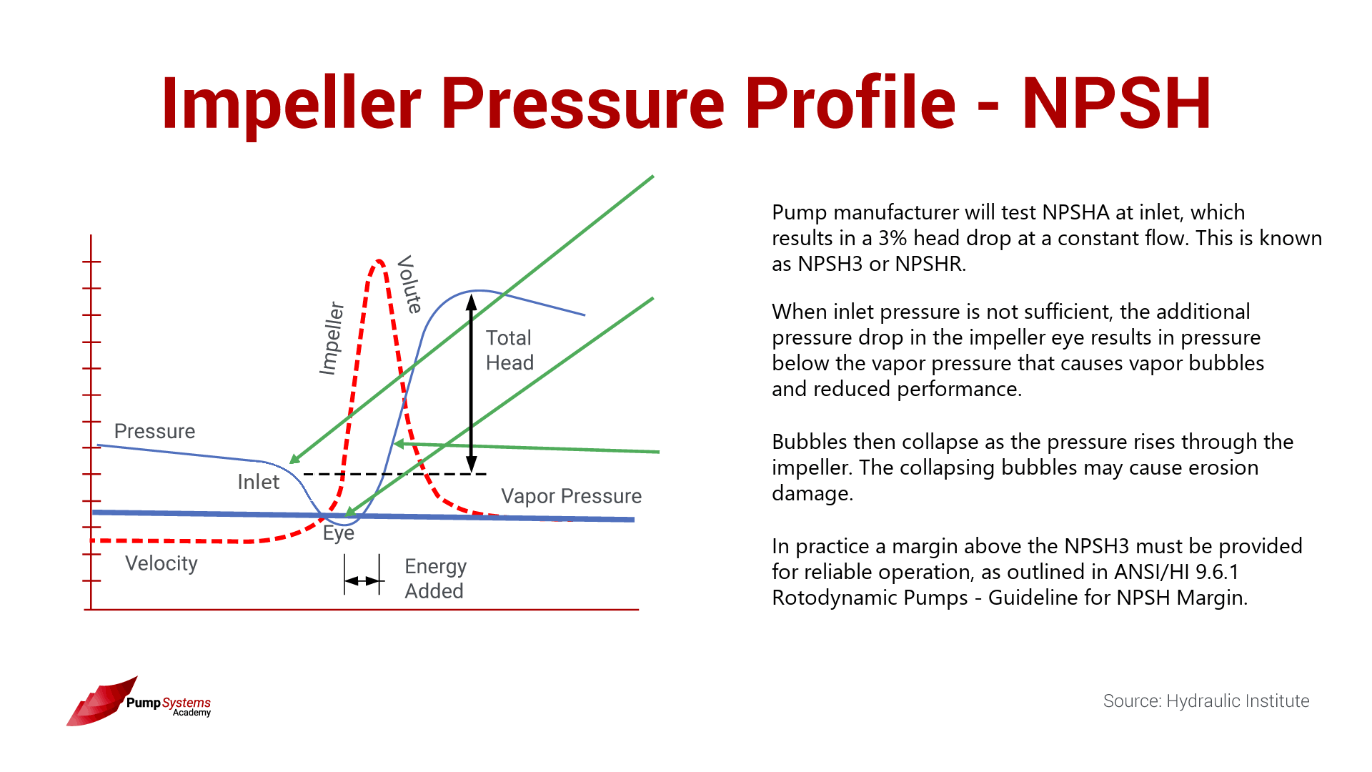
NPSHA must exceed NPSHR for reliable operation. ANSI/HI 9.6.1-2024 updated the guidance so that manufacturer-supplied NPSHR must be greater than or equal to tested NPSH3. Do not treat legacy NPSH3 values as your only margin basis without confirming the current standard requirement.
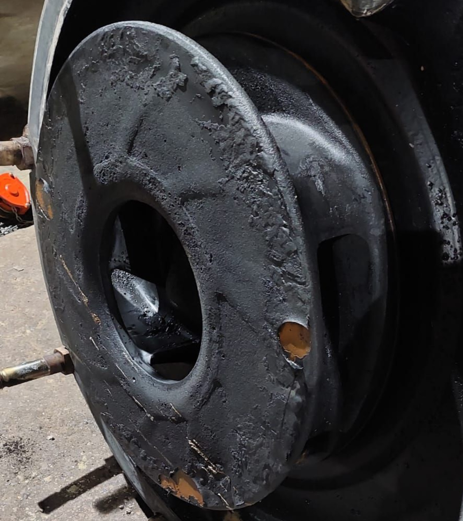
Cavitation from insufficient NPSH margin attacks the impeller eye, producing pitting that looks like a sponge surface. It is often misdiagnosed as erosion because both remove metal. The difference: cavitation pitting has a rough, porous texture in a concentrated band. Erosion produces smoother, directional wear patterns. If you see eye pitting but your suction pressure gauge says NPSHA is fine, check for entrained air, a partially blocked suction line, or a clogged strainer that reduces effective NPSHA at the impeller.
If you need a deeper treatment of suction piping, NPSHA calculation, and cavitation mechanisms, refer to our centrifugal pump impellers guide.
Clearance
Front clearance on open and semi-open impellers and wear ring clearance on closed impellers define internal leakage. As clearance grows through wear, more flow recirculates from discharge back to suction instead of leaving the pump. You see discharge head and flow drop while power draw may stay nearly the same.
Check clearances at every inspection. Compare them against OEM limits. If you schedule impeller replacement based on hours alone without measuring clearance, you are guessing.
For a deeper treatment of wear ring clearance, internal recirculation, and efficiency loss, see our pump wear ring clearance guide.
A note on trimming
Trimming reduces impeller diameter to shift the curve down. The affinity-law screening is:
$$ \frac{Q_2}{Q_1} \approx \frac{D_2}{D_1} \quad\quad \frac{H_2}{H_1} \approx \left(\frac{D_2}{D_1}\right)^2 \quad\quad \frac{P_2}{P_1} \approx \left(\frac{D_2}{D_1}\right)^3 $$
These relationships hold only for similar operating conditions and small diameter changes. Use them as a sanity check, not a final selection tool. DOE Tip Sheet #7 cautions that excessive trimming can create an impeller/casing mismatch and should not go below the minimum diameter shown on the pump curve.
Trim is an adjustment after selection, not a substitute for it. For the full comparison of trimming versus VFDs, see our impeller trimming vs VFD guide.
Read Wear Patterns Before Repeating the Same Failure
A pulled impeller is a diagnostic report. If you do not read it, you are selecting the next one blind.
Leading-edge wear
Erosion concentrated on the vane leading edges and the pressure side near the inlet signals high inlet velocity, off-design flow, or sharp angular particles. Before reordering the same impeller, check whether the pump is running at a flow far from BEP or whether the inlet piping is creating swirl or uneven velocity distribution.
Eye cavitation pitting
Pitting at the impeller eye, especially on the suction side of the vanes, points to insufficient NPSH margin or entrained air. Measure NPSHA and compare to NPSHR at the actual operating flow. Inspect suction piping for air leaks, vortex formation in the sump, or a partially blocked strainer. If NPSHA is adequate and no air source is found, check whether the impeller eye diameter or inlet angle is mismatched to the flow range.
Shroud thinning
External shroud thinning on closed impellers follows the path of solids recirculating between the impeller and the casing liner. Internal thinning between the shrouds indicates high internal velocities. Both are accelerated when the pump runs far from BEP or when the slurry carries angular fines. Compare wear location to the predicted velocity distribution at your operating point.
Asymmetric wear
Uneven wear from vane to vane or shroud to shroud suggests a hydraulic problem upstream: an elbow too close to the suction flange, a partially open valve, uneven sump approach flow, or internal recirculation that favors one side. Fix the hydraulic condition before selecting a replacement impeller. A different geometry will not solve uneven loading.
Casing versus impeller wear mismatch
If the impeller is destroyed but the casing and liner show minimal wear, the material selection may be the issue. If the casing wears faster than the impeller, the clearance is growing and accelerating impeller wear through recirculation. Match the material strategy across the entire wet end, not just the impeller.
✓Decision Point: Before reordering an impeller, pull inspection records and answer three questions. One: is the wear pattern consistent with the dominant risk you identified during the last selection? Two: has the operating point shifted since the last baseline curve was recorded? Three: does the slurry sample from this campaign match the data used to select the current impeller? If the answer to any of these is no, do not repeat the same order.
Build the Selection Checklist for Maintenance and Procurement
The difference between a repeat failure and a successful impeller run often comes down to what data was collected before the order was placed. Use this checklist when preparing an impeller replacement or upgrade.
Process data
| Data Point | Why It Matters |
|---|---|
| PSD (d50, d90, top size) from a representative sample | Determines passage size and vane count |
| Solids SG and concentration (wt% and vol%) | Determines power draw and settling behavior |
| Particle shape (rounded vs angular) and Mohs hardness | Predicts wear mechanism: erosion vs impact |
| Slurry pH, temperature, and chemical composition | Narrows material compatibility |
| Entrained air or foam observed in sump/suction | Reduces NPSHA; may require recessed impeller |
| Tramp or oversize history (screens bypassed, liner fragments) | Drives open or recessed selection |
Pump and system data
| Data Point | Why It Matters |
|---|---|
| Pump model, speed, and current impeller diameter | Baseline for curve comparison |
| Measured flow, head, and power at normal duty | Confirms actual operating point vs BEP |
| NPSHA calculation from suction piping and sump level | Verifies margin above NPSHR |
| Current clearances (front clearance, wear ring gap) | Quantifies recirculation loss |
| Operating hours since last impeller change | Benchmarks wear life |
| Duty cycle: continuous, intermittent, starts/stops per day | Affects fatigue and impact loading |
| VFD or fixed speed; speed range if variable | Influences NPSHR and BEP offset |
Failure history and inspection
| Data Point | Why It Matters |
|---|---|
| Photos of the pulled impeller: eye, vanes, shrouds, back shroud | Documents wear pattern |
| Photos of the casing, liner, and volute from the same inspection | Reveals casing vs impeller wear mismatch |
| Flow/head trend data since last baseline | Detects gradual wear before failure |
| Vibration trend at 1X and vane pass frequency | Identifies imbalance or hydraulic instability |
| Seal or bearing failure history during this impeller's run | May indicate hydraulic problems, not just seal issues |
| Previous impeller geometry, material, and run life | Prevents repeating a design that failed for a reason you can now see |
Gather this data before the next shutdown ends. If it takes an extra shift, that shift costs less than repeating a failure six weeks later.
If you have slurry data, pump curves, operating trends, and photos of a pulled impeller, contact Dynapro before the next shutdown. Our team can help you cross-check the impeller geometry, material, and operating point against your actual service conditions.
When to Link Out Instead of Solving Everything Here
Some topics are too deep for a single article. Here is where to go next and why.
Impeller materials in depth
This article treats material selection as a decision gate after geometry is chosen. For the full engineering comparison of high chrome white iron, natural rubber, polyurethane, and ceramic grades — including hardness ranges, pH limits, temperature ceilings, and application-specific selection logic — see our slurry pump impeller materials guide.
Impeller fundamentals
If you need a broader treatment of impeller types, hydraulic theory, and design principles beyond slurry service, start with our centrifugal pump impellers guide.
Reverse vane impellers
Reverse vane impellers are a special design that uses back vanes to reduce axial thrust and seal chamber pressure. They suit specific slurry and sealing applications. For selection criteria, design limits, and field considerations, see our reverse vane impeller selection guide.
Trimming versus VFDs
When the duty point does not match the impeller, you can trim or add a VFD. Each has different effects on efficiency, wear, NPSHR, and total cost. See our impeller trimming vs VFD comparison.
Clearance and internal recirculation
Clearance growth drives internal recirculation, which accelerates wear and steals efficiency. For the full relationship between wear ring gap, recirculation, vibration, and head loss, see our pump wear ring clearance guide.
System-level slurry pumping efficiency
When the problem is broader than the impeller — piping losses, settling velocity, duty point mismatch, or control strategy — our slurry pumping efficiency guide addresses the full system.
FAQs
Which impeller is best for abrasive slurry?
It depends on particle size, shape, and concentration as much as hardness. For hard angular fines with a controlled top size, a closed impeller with high-chrome white iron or polyurethane can deliver the longest wear life. For coarse, sharp solids with tramp risk, an open or semi-open impeller in a wear-resistant material is usually the safer choice. Define the dominant wear mechanism first, then match geometry and material to it.
When should I choose a recessed or vortex impeller?
Choose a recessed impeller when plugging is the dominant risk and efficiency is secondary. Sumps handling unpredictable tramp, stringy material, rags, or entrained air are the classic cases. If your pump plugs more than twice per shutdown cycle and upstream screening is unreliable, a recessed design may save more downtime than the efficiency loss costs.
How does vane count affect slurry pump performance?
Fewer vanes create larger passages and reduce plugging risk but concentrate hydraulic load on each vane, increasing local velocity and wear. More vanes smooth flow and improve efficiency but limit the maximum solid size that can pass. For abrasive slurries with controlled top size, 4-5 vanes often balance wear and passage. For plugging-prone service, 2-3 vanes or a recessed design may be required.
Is high chrome always better than rubber?
No. High chrome white iron resists cutting abrasion from hard angular particles but can crack under repeated impact from large solids. Rubber resists impact and fine-particle erosion well but tears when cut by sharp particles or degraded by solvents and high temperatures. Match the material to the wear mechanism and chemistry, not to a default preference. See the full comparison in the materials article linked above.
Can I trim a slurry pump impeller?
Yes, within the limits published on the OEM pump curve. Trimming reduces diameter, which shifts the curve down. Use the affinity laws as a screening estimate only. Excessive trim creates clearance mismatch between the impeller and casing, which accelerates wear and can degrade head more than the affinity laws predict. If the required trim exceeds the OEM minimum diameter, consider a VFD or a different impeller.
What wear pattern means the wrong impeller was selected?
Leading-edge erosion combined with eye cavitation pitting often means the impeller is running at a flow far from BEP, regardless of geometry. Asymmetric wear from vane to vane signals an upstream hydraulic problem, not a geometry failure. Shroud thinning on both sides that outpaces casing wear usually points to excessive internal velocity for the material chosen. Before calling it a wrong selection, rule out NPSH problems, off-BEP operation, suction piping issues, and clearance growth.
---
References
- ANSI/HI 12.1-12.6 Rotodynamic Centrifugal Slurry Pumps for Nomenclature, Definitions, Application, and Operation
- ANSI/HI 9.6.1 Rotodynamic Pumps Guideline for NPSH Margin
- Understanding the 2024 Updates to ANSI/HI 9.6.1 — NPSHR vs NPSH3 Transition and NPSH Margin
- ANSI/HI 9.6.3 Rotodynamic Pumps Guideline for Operating Regions
- HI Data Tool — Slurry Properties for Pump Systems
- U.S. Department of Energy, Pumping Systems Tip Sheet #7 — Trim or Replace Impellers on Oversized Pumps


