

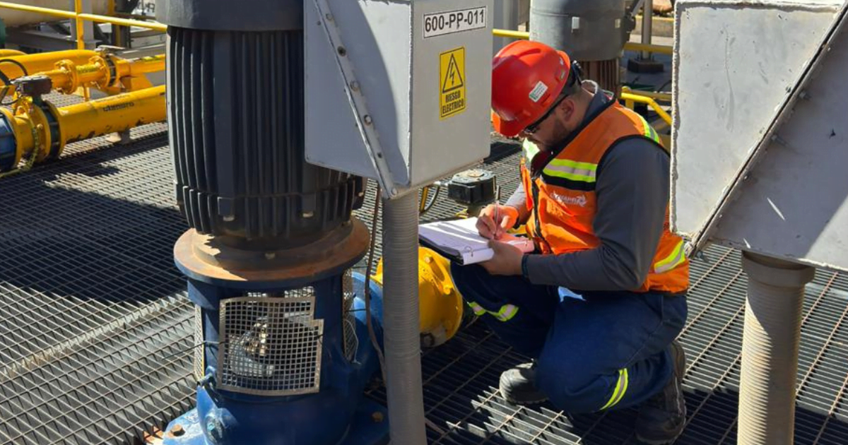
A submersible pump may restart and still not be ready for service. Submersible pump maintenance is complete when its condition has been verified, measurements are within applicable limits, protections are active, and the decision is documented; not simply when the equipment starts.
This guide organizes that sequence for industrial rotodynamic submersible pumps, provided that the exact installation, operation, and maintenance (IOM) manual for the model is available. It does not replace that IOM or your site's energy control, lifting, or confined-space program. Internal motor repair, rewinding, and unauthorized energized electrical testing are outside its scope.
You will work through nine phases: prepare, secure, inspect, service, measure, decide, close, test, and record. Without the IOM and a site procedure, limit the work to identification, external inspection, data collection, and escalation.
Key Terms
– IOM: The model-specific installation, operation, and maintenance manual; the authorized source for steps, limits, and acceptance criteria.
– Baseline: Initial measurements of flow rate, pressure, current, and condition, taken with a documented method and instrument.
– Hold point: A point at which work stops until a defined verification, measurement, or authorization has been completed.
– LOTO: Lockout/tagout of energy sources, per the site's energy control program.
– Acceptance criterion: A limit or condition from the IOM or the site standard that defines when a verification passes.
– Nonconformity: A finding or measurement outside the acceptance criteria, recorded and pending a decision.
Procedure Scope, Limits, and Authority
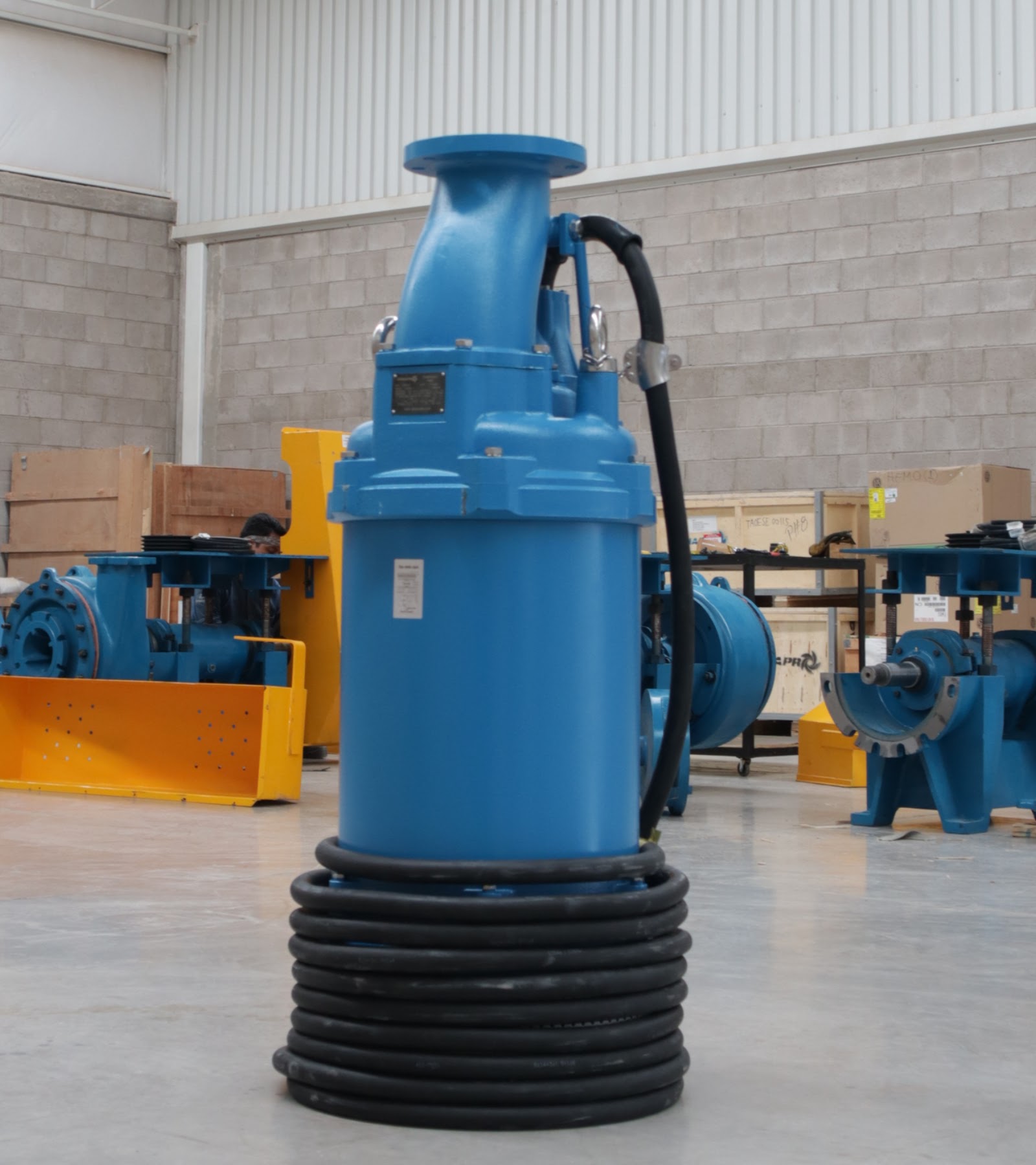
This guide covers rotodynamic submersible pumps in industrial service and separates work levels with different authority requirements. The submersible pump hub covers types, applications, and selection; here, you revisit only what is essential for maintenance.
| Work level | Scope in this guide | Required authority |
|---|---|---|
| Non-invasive inspection | Identification, external visual review, data, and trends | Authorized personnel and applicable IOM |
| Authorized service | Cleaning and consumables covered by the IOM | Authorized personnel and approved spare parts |
| Specialized testing | Continuity, insulation, and integrity | Electrician, specialist, or OEM |
| Repair | Motor, winding, cable, seal, or hydraulics | Authorized shop or OEM |
Non-invasive inspection does not require opening the equipment: it checks the cable, cable entry, casing, screen, supports, and external signs such as leaks, corrosion, noise, or vibration. Repair typically requires a repair shop or the OEM and is outside this guide's scope. The guide covers preparation, external inspection, authorized cleaning, measurement, and decision-making; it excludes rewinding, energized testing, entry into confined spaces, and lifting without a site procedure.
Authority is ranked as follows: the IOM governs steps, limits, and acceptance criteria; your site's procedures govern energy, lifting, and confined spaces. ANSI/HI 14.4 defines the expected scope of those manuals, which is why every phase depends on the IOM.
When to Perform Submersible Pump Maintenance
Maintenance frequency does not come from a universal calendar; it comes from the model's IOM, the criticality of the service, the observed condition, and the cost or risk of failure. The U.S. Department of Energy recommends basing frequency on the manufacturer's recommendation, criticality, downtime cost, and failure risk. The IOM sets the initial maintenance intervals; you adjust inspection points based on what condition and trend data show.
iNote: Intervals, insulation resistance, torque values, clearances, and allowable leakage are IOM or site-standard values; do not generalize them from another brand or model.
| Trigger | What to check | Evidence | Applicable limit | Action | Responsible party |
|---|---|---|---|---|---|
| IOM interval | Cable, cable entry, casing, screen, supports | Photos and records | IOM visual criteria | Perform or reschedule | Authorized maintenance personnel |
| Trend (current, flow rate, pressure) | Against baseline and pump curve | Comparable series | IOM or site limits | Adjust frequency or service the equipment | Maintenance and specialist |
| Condition (leak, noise, vibration) | Associated component, without opening the equipment | Observation and measurement | IOM criteria | Hold point and decision | Authorized maintenance personnel |
| Process or fluid change | Operation vs. design | New service data | IOM expected conditions | Revalidate with the OEM | Engineering and OEM |
| Alarm or performance loss | Protections, flow rate, current | Alarm log | Protection limits | Service or shut down | Operations and maintenance |
| Abnormal event (impact, flooding, dry running, improper lifting) | Cable, casing, seal, and accessible parts | Event record | IOM and risk assessment | Keep out of service | Authorized supervisor |
| After a repair | Integrity and function | Documented test | IOM and contractual criteria | Accept or return | Authorized personnel, repair shop, or OEM |
Three hypothetical examples illustrate the logic; none describes a real installation:
- Dewatering in an open-pit mine: with a single pump, criticality pushes frequency and inventory to the high end the IOM allows.
- Wastewater wet well with a standby unit: per-unit criticality is lower, but exposure to solids shortens the screen inspection interval.
- Mobile construction pump: the service changes with every relocation; take a new baseline before using the trend.
When corporate intervals, forms, and spare parts are already covered by your industrial pump preventive maintenance plan, keep them there; this guide adds the submersible-specific aspects.
Safety, Competence, and the Safe State
Once the frequency is defined, the next step is not to open the pump but to establish a safe state in accordance with your site's energy control program: electrical energy, stored hydraulic energy, suspended loads, the wet-well atmosphere, and fluid contamination. Each hazard is controlled through the site's procedure.
In the U.S., OSHA 29 CFR 1910.147 requires a hazardous energy control program for servicing and maintenance, including verification of lockout. It is a U.S. general industry framework: in another jurisdiction, local law applies, and your site's program comes first in all cases.
🔴Caution: Do not replace your site's lockout/tagout procedure with a generic list. If the permit, isolation, or safe-state verification is unresolved, work does not begin.
Competence also has levels: site-authorized personnel for preparation and inspection; an electrician or specialist for insulation and continuity tests; and the OEM or a repair shop for motor and seal integrity. If the qualified person is unavailable, the task is rescheduled or escalated; it is not improvised.
Documents, Tools, Instruments, and Baseline
With the safe state defined, gather what the procedure will require:
| Input | What it is used for | Hold point if missing |
|---|---|---|
| Current model-specific IOM | Defines steps, limits, lubricants, and closeout | Do not open or adjust |
| Nameplate and identification | Confirms configuration and traceability | Resolve the identity before continuing |
| History and work order | Shows failures, operating hours, and previous measurements | Establish a baseline first |
| Pump curve and operating point | Compare flow rate, head, and current | Do not attribute a deviation to the pump alone |
| Site procedures | Govern energy control and lifting | Do not start the affected phase |
| Approved spare parts | Confirm lot and compatibility | Do not install a part without traceability |
| Calibrated instruments | Support reliable readings | Do not accept a measurement without calibration |
The baseline is the starting point for every trend: flow rate, pressure or head, current, and condition, taken with a documented method, instrument, and operating point. If the equipment changes service or location, establish a new baseline before using the historical data.
Pre-work checklist
- ☐Equipment identified by nameplate and serial number; matches the available IOM.
- ☐Current IOM and site procedures (energy, lifting, confined spaces) available.
- ☐Work permits current and scope defined.
- ☐Energy and pressure controlled in accordance with the site program; safe state verified.
- ☐Wet-well condition assessed: level, atmosphere, and access.
- ☐Lifting, access, and fluid contamination managed: drainage, containment, and PPE.
- ☐Instruments calibrated and spare parts approved by part number.
- ☐Work order opened with reason, scope, and baseline.
Phase-by-Phase Submersible Pump Maintenance Sequence
With the scope, controls, and baseline prepared, execute the nine phases in order; each ends when its evidence authorizes the next step. If a condition is not met, the phase stops and the nonconformity is documented. Opening steps, torques, clearances, and tests are defined in the IOM; this guide defines the route, not the values.
⚠️Warning: Do not open the equipment or run energized tests if the model IOM does not define the method, limits, and authorization. Without that IOM, limit the work to preparation, external inspection, data collection, and escalation.
1. Prepare the scope and the authorized basis
Link the work order to the equipment, the IOM, and the reason. Define what you can inspect, clean, measure, or replace and the limits that will decide acceptance, repair, or escalation. If the model does not match, leave the equipment identified and out of scope.
2. Establish and verify the safe state
Apply the site's energy control program and control pressure, backflow, movement, and stored energy. Verification follows the written method and remains the responsibility of authorized personnel. Hold point: without a verified safe state, no work may proceed.
3. Document the condition before cleaning
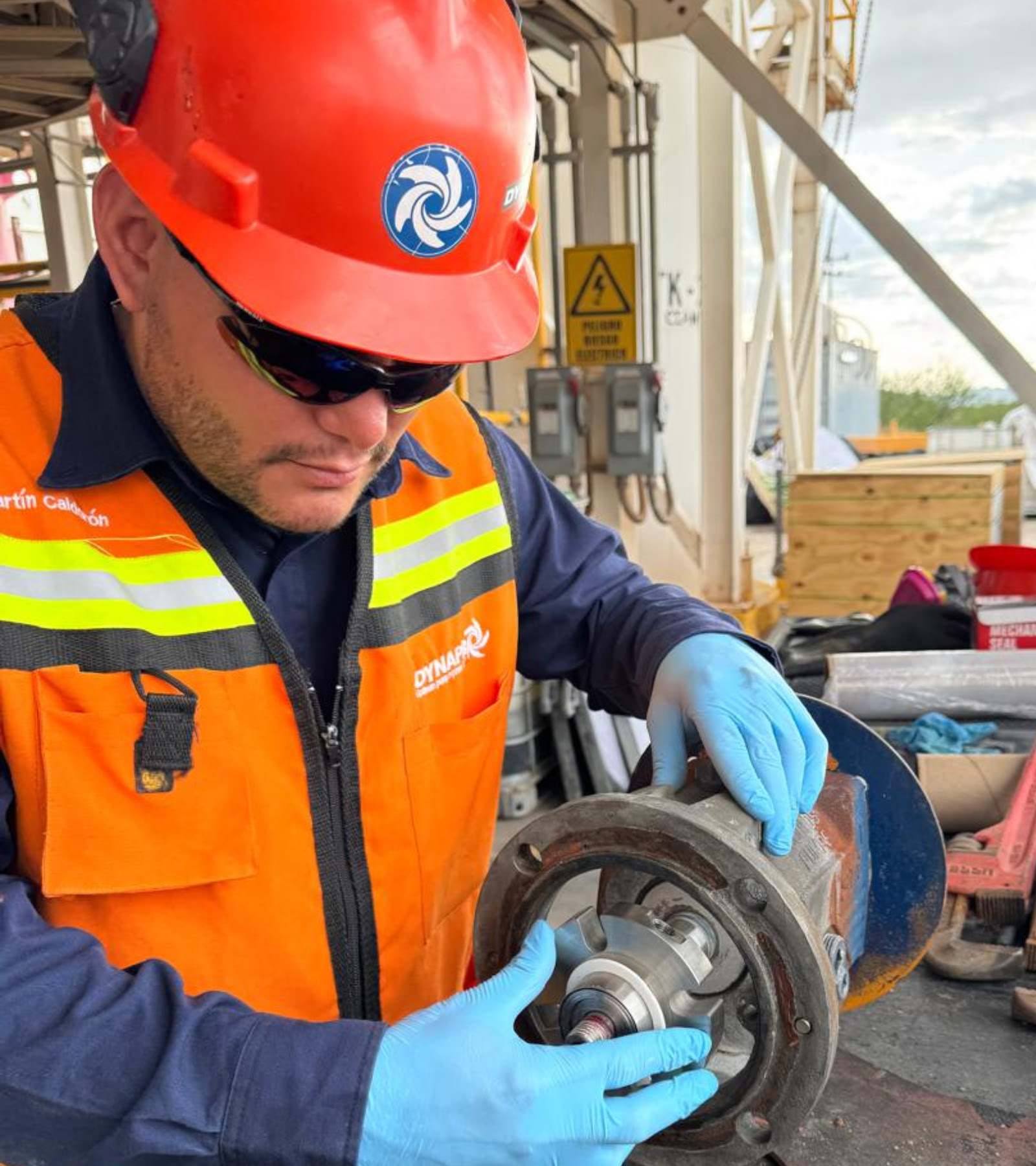
Photograph or record the cable, cable entry, casing, screen, connections, supports, and visible deposits. Look for cuts, crushing, abrasion, corrosion, loose parts, leakage, or trapped material. Document before cleaning: cleaning can erase the evidence of the ingress path or the wear pattern.
4. Remove, clean, and inspect within the authorized scope
Perform only what the IOM authorizes. If the pump must be moved, use the site's lifting procedure and the manufacturer's lifting points; protect the cable from tension, twisting, and edges. Clean the screen and permitted surfaces, then reinspect the cable, cable entry, casing, screen, supports, and accessible components against the IOM criteria; document corrosion, deformation, wear, leakage, or obstruction. An obstruction that cannot be removed using the authorized method is a hold point.
5. Measure and verify
Measure flow rate, pressure or head, and current at the same operating point and with the same instrument and method used for the baseline, and record the instrument and its calibration.
6. Decide at the hold point
Compare against the IOM and site-standard limits. If everything is within limits, continue; if not, apply the matrix in the next section.
7. Close out the physical work
Reinstall guards, connections, and supports per the IOM and confirm that no tools or debris remain. Energy locks and tags are removed only by the person authorized by the site procedure.
8. Run the authorized controlled test
Start and test in accordance with the IOM or site procedure, with abort criteria established and protections active. Verify rotation direction, flow rate, pressure, and current against the baseline. Do not bypass an alarm or raise a limit to complete the test.
9. Record and hand over
Document results, measurements, parts, exceptions, and the next date, and hand the equipment over to operations. The hold point is not the end of maintenance: it is the transition to a documented decision.
There are three critical hold points: safe state (phase 2), measurements within the applicable limits (phase 6), and a test with no abort condition (phase 8). If any one fails, work does not proceed.
What to Measure and How to Interpret the Trend
The sequence produces data; the decision depends on how you interpret them. A single value rarely determines the decision on its own: the trend does, within the IOM and site limits. A reading means something only when compared with a baseline taken at the same operating point, using the same instrument and method. The DOE groups inspection into categories such as leakage, motor, and efficiency, and emphasizes the value of trend records.
| Variable | What to observe or measure | What it may indicate | Condition requiring escalation |
|---|---|---|---|
| Motor current | Reading against baseline and nameplate | Obstruction, wear, or operating point change | Deviation outside the IOM limit or sustained trend |
| Flow rate and pressure or head | Reading against the pump curve | Impeller wear, suction obstruction, or system change | Performance outside the pump curve under the same conditions |
| Vibration or noise | Observation or measurement where the IOM defines it | Wear, rubbing, or imbalance | Noticeable change or value outside the applicable limit |
| Surface temperature | Spot measurements | Operation outside intended conditions or restricted cooling | Upward trend with no process change |
| Leakage or moisture | Seal and cable entry inspection | Loss of barrier integrity | Any sign triggers the hold point |
| Insulation | Only with the IOM method and limit | Moisture ingress or winding deterioration | Value outside the IOM limit |
| Screen or strainer | Visual inspection | Obstruction, deformation, or abrasion | Restriction affecting suction |
Trends are comparable only when the operating point, instrument, and method are the same. If the pump has changed service, fluid, or location, the previous baseline is no longer valid: establish a new one. Always measure at the same operating point—for example, with the same discharge opening—and record the instrument used: a trend that mixes conditions is noise, not information.
Hold Points: Clean, Repair, Replace, or Escalate
Trend interpretation ends with a decision. Stop when the evidence is outside the IOM limits or your authority. There are four outcomes: clean within the authorized scope, have it repaired by a specialized shop or the OEM, replace using reselection data, or escalate.
🔴Caution: Stop and escalate if there is cable or seal damage, evidence of fluid ingress, unacceptable insulation, an obstruction you cannot remove safely, an untraceable part, or a discrepancy between the equipment and the IOM. Continuing with any of these conditions unresolved puts the motor and people at risk.
| Finding | Evidence | Action | Authority |
|---|---|---|---|
| Missing IOM or uncertain identity | Nameplate compared with the document | Stop; obtain the correct IOM or verify traceability | Supervision and OEM |
| Cable or seal damage | Cut, abrasion, moisture, or leakage | Hold point; do not operate | Specialist or OEM |
| Fluid ingress | Internal moisture or loss of barrier integrity | Hold point; integrity test | Repair shop or OEM |
| Uncalibrated instrument | Expired calibration certificate | Stop the measurement; recalibrate | Metrology and maintenance |
| Unacceptable insulation | Reading outside the IOM limit | Hold point; specialized testing | Electrician or repair shop |
| Non-traceable part | No part number or batch | Do not install; obtain an approved spare part | Supervision and OEM |
| Uncontrolled lifting or confined space | No approved procedure or means | Stop; activate the procedure | Site safety |
| Result outside the OEM limit | Measurement compared with the IOM | Nonconformity; decide | Maintenance and OEM |
Submersible pump repair—motor, cable, seal, or insulation—typically requires a specialized repair shop and an integrity test before the equipment can be accepted. Whether to repair or replace is not based on age; it is based on evidence against OEM limits, the cost and risk of failure, and the available traceable spare parts. If the finding requires reselection, the data are in the guide to selecting industrial pumps.
A compatible spare part is not validated by appearance: it requires identification by part number, materials, dimensions, performance, and manufacturer documentation. Compatibility is confirmed by the OEM or the applicable technical documentation.
If the finding requires identifying a compatible spare part or validating a repair decision against your model, contact the Dynapro team for technical identification.
Controlled Verification and Return to Service
Once the decision has been made, the pump is still not ready to return to service. Returning to service does not mean the pump starts: it means the condition has been accepted and documented. A pump that starts with an open nonconformity remains at risk.
Post-work and return-to-service checklist
- ☐Guards, connections, and supports installed per the IOM; area cleared of tools and debris.
- ☐Protections active and verified.
- ☐Controlled test performed and observed per the IOM or site procedure.
- ☐No abort condition: no abnormal vibration or noise, no leakage, and no protection trip.
- ☐Final measurements within the applicable limits and recorded.
- ☐Formal handover to operations with condition and next dates.
Abort criteria are defined by the IOM or the site procedure: at minimum, abnormal vibration or noise, visible leakage, a protection trip, or a reading outside the applicable limit. Restarting the test without correcting the cause is not a verification.
When the contract requires mechanical and electrical integrity tests with formal acceptance, ANSI/HI 11.6 defines their scope for rotodynamic submersible pumps. These are contractual or laboratory tests, not a field method you can improvise.
Records and Maintenance Plan Improvement
The record turns one intervention into evidence for the next. If it was not documented, it did not happen for the plan: it does not support trends, justify spare parts, or defend a decision in an audit.
Minimum work order fields:
- Identification: serial number, location, date, and operating hours.
- Reason, scope, and initial condition with baseline measurements.
- Measurements taken, including instrument and calibration.
- Parts and batches used or found, and limits applied (IOM or site standard).
- Photos of findings and closeout, result, and nonconformities with their disposition.
- Personnel responsible for execution and verification.
- Next date or intervention trigger.
Separate the effect of maintenance from other changes: a variation in flow rate may come from the level, valves, fluid, or control system. Recording those conditions prevents unsupported attribution of improvement or deterioration to the intervention.
With these fields, the plan stops being a calendar and becomes an improvement loop: trends adjust frequency, history justifies inventory, and recurring nonconformities show where the method must change. Close each intervention with written acceptance: condition and measurements within applicable limits, nonconformities closed or escalated, protections verified, and the next date defined. If a finding has no assigned limit or authority, escalate it to the OEM or specialist before returning the equipment. Submersible pump maintenance is complete when the evidence has been recorded and the decision documented, not when the pump restarts.
FAQs
How often should a submersible pump be maintained?
There is no universal interval. Use the IOM interval and adjust it for criticality, condition, and trends, within what the IOM and site standard allow.
What can be checked without disassembling the pump?
You can inspect everything external: the cable, cable entry, casing, screen or strainer, supports, and observable leakage, corrosion, noise, and vibration. You can also measure flow rate, pressure, and current against the baseline. Any opening of the equipment is subject to the IOM.
What does seal or cable damage indicate?
It indicates that an integrity barrier may be compromised. The seal limits fluid ingress; the cable and its entry maintain electrical and sealing integrity. If you find cuts, abrasion, moisture, or leakage, apply the hold point and escalate the finding: do not operate with a compromised barrier.
When should the pump be repaired or replaced?
When the evidence indicates it: measurements outside the OEM limit, a failed integrity test, an unfavorable cost and failure risk, or a lack of traceable spare parts. Replacement may be appropriate when the finding requires the pump to be reselected for another service or when repair cannot restore an acceptable, verifiable condition.
Which tests require specialized personnel?
Insulation, continuity, and motor and seal integrity tests. They are performed by an electrician or specialist using the method and limits in the IOM or contractual standard. They are not a universal field check.
What should the work order record?
At a minimum: identification, date and operating hours, reason, initial condition, measurements with instrument and calibration, parts and batches, photos, limits used, result, nonconformities, responsible personnel, and the next date. Without these fields, there is no defensible trend.
References
- OSHA, The control of hazardous energy (lockout/tagout), 29 CFR 1910.147: https://www.osha.gov/laws-regs/regulations/standardnumber/1910/1910.147
- U.S. Department of Energy, Improving Pumping System Performance: A Sourcebook for Industry, 2nd ed., 2006: https://www.osti.gov/biblio/882946
- U.S. Department of Energy, Maintain Pumping Systems Effectively — Pumping Systems Tip Sheet #5, 2005: https://www.osti.gov/biblio/1216267
- Hydraulic Institute, ANSI/HI 14.4 Rotodynamic Pumps Manuals for Installation, Operation, and Maintenance, 2024: https://www.pumps.org/product/ansi-hi-14-4-rotodynamic-pumps-manuals-for-installation-operation-and-maintenance/ (paywalled)
- Hydraulic Institute, ANSI/HI 11.6 Rotodynamic Submersible Pumps for Mechanical and Electrical Acceptance Tests, 2022: https://www.pumps.org/product/ansi-hi-11-6-rotodynamic-submersible-pumps-for-mechanical-and-electrical-acceptance-tests/ (paywalled)


