

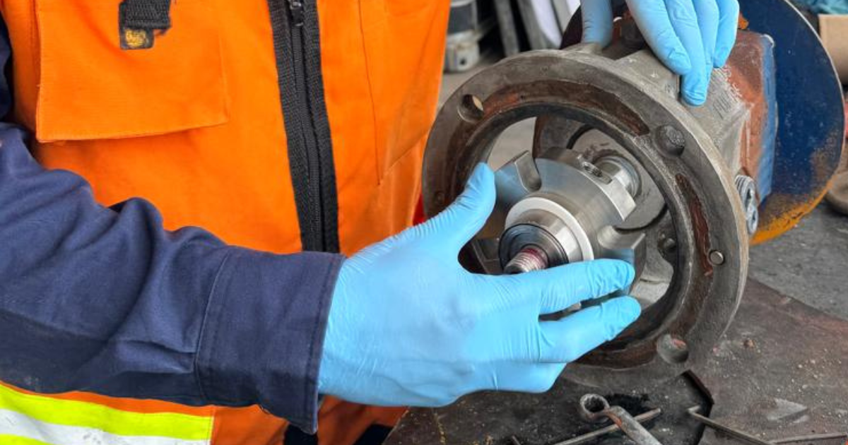
You replaced the mechanical seal on Friday. By Monday it's leaking again. Back at the shop they ask whether you checked the shaft sleeve, runout, bearings, and flush before installing the new seal. If you didn't, the new seal simply repeated the failure.
In this field guide we cover how to replace a mechanical seal on a centrifugal pump: what to check before touching a single bolt, how to inspect so the leak doesn't come back, which mistakes can cause a new seal to fail in hours, and how to perform a controlled startup after the replacement. By the end, you'll have a checklist you can take to your next intervention.
Make sure you're clear on these terms before proceeding:
Key Terms
– Mechanical seal: A device with two sealing faces separated by a thin fluid film that controls leakage where the shaft passes through the casing.
– Rotating face: The seal face that rotates with the shaft.
– Stationary face: The fixed face housed in the gland or seal chamber.
– O-ring / Elastomer: Secondary seal between components; it may be static or dynamic depending on the seal design (FKM, EPDM, FFKM, NBR depending on fluid and temperature).
– Gland: The part that closes the seal chamber and houses the stationary face.
– Shaft sleeve: A protective sleeve over the shaft that provides the contact surface for the O-rings.
– Flush: Fluid routed to the seal chamber to cool, clean, and lubricate the faces; it may come from the process or an external source, depending on the API 682 plan.
– Barrier / Buffer: Fluid between dual seals; the barrier isolates the process from the environment, the buffer cushions at lower pressure.
– Runout: Radial or axial deviation of the shaft or sleeve that loads the faces.
Before Replacing the Seal: Confirm Safety, Cause, and Replacement Part
🔴Caution: Never service a pump without applying lockout/tagout in accordance with OSHA 29 CFR 1910.147. Verify zero energy at all isolation points: electrical, hydraulic, pneumatic, and thermal. Accidental energization during maintenance can be fatal.
The rush to change the seal and get the pump back into production is the first enemy of a job done right. Stop. Before touching the first bolt you need three things confirmed: safety, probable cause of failure, and the correct spare.
Isolate the pump. Lock it out. Depressurize. Drain completely and let it reach a safe temperature. If the fluid is hazardous — chemical, hot, flammable, or toxic — consult the site safety procedure. Hazardous energy control is not a formality: according to NIOSH, unexpected release of stored energy remains a documented cause of serious injuries in industrial maintenance.
Identify the seal by its part number and have the pump and seal manufacturer manuals at hand. Without those two documents, every step you take is a gamble. Compare the new seal with the old one before disassembly: dimensions, face materials, elastomers, orientation, and flush plan must match.
Resist the temptation to order the seal and start disassembling. If you haven't identified the root cause, the new seal will inherit the same fate.
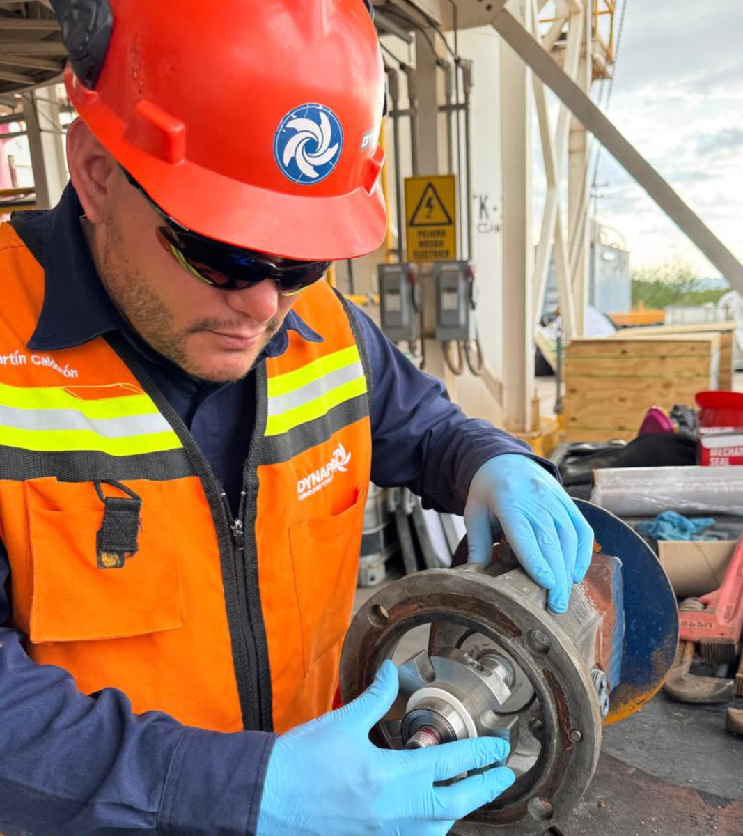
Why a Mechanical Seal Fails in a Centrifugal Pump
A mechanical seal works because two faces — one rotating, one stationary — are separated by a very thin fluid film. That film lubricates, cools, and reduces friction to controlled levels. The seal is not a single part: it's a system that depends on the condition of the shaft, the sleeve, the bearings, the coupling, the flush, and the operating conditions.
When the film between faces breaks down, the seal fails quickly. The most common field causes:
- Dry running: Starting without priming, losing prime due to poor suction, or shutting off the flush. Without fluid between the faces, friction destroys the film in seconds. The faces burn.
- Inadequate flush: In services with solids, hot fluids, or fluids that crystallize, the faces need external cleaning and cooling. A flush with low pressure, obstructed, or incorrectly set up according to the API 682 plan specified for that seal leaves the faces operating under conditions they were not designed for.
- Vibration and cavitation: Cavitation generates pressure pulses that momentarily open the seal faces. Solids, air, or vapor enter. Vibration from misalignment or damaged bearings imposes lateral movement that the faces cannot compensate for.
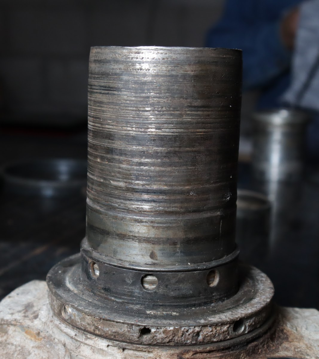
- Damaged shaft sleeve: A scored, pitted, or out-of-tolerance roughness sleeve will not seal even with a new seal. The fluid finds a path through the imperfections under the O-rings.
- Material incompatibility: Elastomers that swell, harden, or crack because the material cannot withstand the fluid, temperature, or process additives.
For a broader perspective on how mechanical seal applications vary by industry and service, see our specific guide. Here we focus on diagnosis to avoid repeating the failure.
⚠️Warning: Replacing the seal without eliminating the root cause is the number one reason for repeat failure. The faces of the old seal are your best evidence. Save them for inspection before discarding them.
Tools, Spares, and Data You Need to Gather
You need the right gear from the start, not whatever happens to be in the tool cart.
Documents:
- Pump OEM manual and seal manufacturer instructions
- Material data sheet (elastomer compatibility)
- Confirmed seal part number
Spares:
- Complete new mechanical seal, O-rings, and gaskets (do not reuse old ones)
- New shaft sleeve if the current one has scoring, pitting, or wear
- Assembly lubricant compatible with elastomers and process fluid
Tools:
- Standard disassembly tools, dial indicator if runout measurement is required
- Puller if the design requires it, torque wrench if the OEM specifies values
- Camera to document component positions before disassembly
Operating data:
- Discharge and suction pressure before failure, fluid temperature and temperature at the seal area
- Vibration history if available, flush conditions (pressure, flow rate, line condition)
API 682 defines families of sealing plans — flush, barrier, buffer — based on service. If your pump has an active plan, verify that lines, filters, orifices, and instrumentation are working before disassembly. A new seal with a clogged flush operates under the same conditions that caused the previous seal to fail.
General Steps to Replace a Mechanical Seal on a Centrifugal Pump
These steps are a field guide, not a replacement for the OEM procedure. Every pump has its own design. Always consult the manual.
- Isolate and secure. Complete lockout/tagout. Zero energy verified. Pump depressurized, drained, and cool.
- Remove guards and coupling. Guards, covers, and coupling components as per design. Mark the coupling position if you need a reference for reassembly.
- Document. Take photos of the position of each component before removing it. Note the orientation of the gland, the old seal, and any part that could be installed backwards.
- Remove the old seal. Remove the gland. Extract the stationary face and the rotating face following the manufacturer's instructions. Save the faces for diagnosis — do not clean them yet.
- Clean. Clean the stuffing box, the gland housing, and all contact surfaces. No debris, no loose corrosion, no particles.
- Inspect. This is the stage that separates an ordinary seal change from one that won't repeat the failure. The next section covers each inspection in detail.
- Install the new seal. Do not touch the faces with your fingers — skin oils contaminate the sealing surface. Lubricate O-rings and sliding areas only with the recommended lubricant. Seat the stationary face in the gland and the rotating face on the shaft or sleeve according to the design. Do not force it. If something won't go in, something is wrong: inspect, don't push.
- Reassemble. Tighten the gland to the manufacturer's specification. An unevenly tightened gland tilts the stationary face; a loose gland does not compress the static seal. Reconnect flush lines. Reinstall coupling, guards, and covers.
💡Tip: Do not assume the old seal was installed correctly. If you find signs of forced assembly, cut O-rings, a twisted gland, or foreign debris, document everything. That is evidence that the failure may have been installation-related, not design or operation.
Critical Inspections Before Installing the New Seal
This is where a superficial tutorial falls short and your experience makes the difference. Every inspection you skip could be the reason the new seal fails before the next scheduled maintenance.
Old seal faces
Don't toss them without looking. The wear pattern tells you what failed:
- Burned or blued faces: dry running or lack of cooling.
- Deep circumferential scoring: abrasive solids trapped between faces.
- Localized pitting: cavitation.
- Eccentric wear: excessive runout or loose bearings.
- Swollen, sticky, or brittle elastomers: chemical incompatibility or temperature out of range.
Shaft sleeve
Run your fingernail over the O-ring contact area. If you feel scoring, replace the sleeve. A sleeve with roughness out of specification — regardless of the OEM tolerance — will not seal even with a new seal. Also check the diameter and ovality if you have the equipment to do so.
Runout
If the procedure requires it, measure runout on the sleeve or shaft with a dial indicator. The acceptable value is defined by the seal manufacturer, not this article. If the runout exceeds what the seal tolerates, the faces will operate under cyclic loading and service life shortens dramatically.
Bearings and coupling
Bearings with radial or axial play transmit movement to the shaft and, through it, to the seal faces. A misaligned coupling generates vibration that travels directly to the sealing area. Check bearing condition — noise, temperature, clearance — and verify coupling alignment before reassembly.
Stuffing box and gland
Check for corrosion, pitting, solid residue, and flatness of the gland seating surface. Any irregularity can prevent the stationary face from sealing properly against its housing.
Flush system
Open lines. Check filters. Verify that flush orifices are not clogged and that pressure and flow rate match the configured API 682 plan. The flush is not an accessory: in dirty, hot, or crystallizing services, it's what keeps the faces alive.
| Probable Cause of Failure | Evidence on the Old Seal | What to Check Before Installing | Risk if Ignored |
|---|---|---|---|
| Dry running | Burned, blued, or cracked faces | Priming, venting, flush, suction | New seal fails in minutes |
| Abrasive solids | Deep scoring, circumferential grooves | Flush, filter, face hardness | Accelerated wear, premature leakage |
| Chemical incompatibility | Swollen, sticky, or disintegrated elastomers | FKM/EPDM/FFKM/NBR compatibility data sheet | Immediate leakage from degraded elastomer |
| Excessive runout | Eccentric wear, irregular pattern | Measure runout on sleeve or shaft | Permanent cyclic load on faces |
| Loose bearings | Vibration, noise, uneven wear | Radial/axial clearance, temperature, noise | Lateral movement the seal cannot compensate for |
| Cavitation | Localized pitting, impact marks | NPSH, suction, cavitation diagnosis | Face opening, solids and air ingress |
| Scored sleeve | Leak that persists despite new seal | Visual inspection with raking light, roughness | Won't seal even with a new seal |
| Cut O-ring | Lateral leak, deformed O-ring | Assembly lubrication, lead-in chamfers | Immediate leak on startup |
| Inadequate flush | Solids buildup on faces, high temperature | Pressure, flow rate, line cleanliness, filter | The seal operates under the same conditions that caused the previous seal to fail |
✓Decision point: If during inspection you find a scored sleeve, runout out of tolerance, or loose bearings, do not install the new seal yet. Correct the mechanical condition first. Installing a new seal on worn components is investing time and spares in a programmed failure.
If you need to confirm seal compatibility, face materials, elastomers, or operating conditions before working on a critical pump, consult our technical team.
Common Mistakes That Cause a Second Failure
The same mistakes repeat across plants of all sizes. Recognize them before you make them:
- Touching the seal faces with your fingers. Skin oils, sweat, and particles contaminate the sealing surfaces. Wear clean gloves and handle the seal by the body, not the faces.
- Reusing old O-rings. An O-ring costs pennies compared to the downtime of a pump. Always replace them.
- Installing the seal dry when the manufacturer does not allow it. Some seals require assembly lubrication; others come pre-lubricated. Follow the manufacturer's instructions to the letter.
- Tightening the gland without control. If the manufacturer specifies torque, use it. If not, tighten in a cross pattern, gradually, without twisting. An uneven gland tilts the stationary face.
- Ignoring the flush system. A flush with low pressure, clogged, or shut off leaves the faces without cooling or cleaning. In dirty or hot services, this can cause the seal to fail within hours.
- Starting the pump without priming. Dry running burns the faces. Verify full priming and venting before startup.
- Not checking coupling alignment. A misalignment that existed before the seal change will continue generating vibration on the new seal.
- Changing only the seal when the sleeve is scored. The new seal cannot compensate for a damaged surface under the O-rings. Replace the sleeve as well if it is marked.
iCommon mistake: Changing the seal "fast" without diagnosing the root cause. The time you save today you pay for with another unplanned shutdown next week.
Post-Replacement Testing and Controlled Startup
Don't start the pump and walk away. The post-change startup must be controlled and monitored.
Before startup:
- Shaft turns freely by hand when the design allows it. If you feel resistance, stop and inspect.
- Pump fully primed. Open vents. Verify that the suction line has fluid.
- Flush open. Confirm pressure and flow rate according to the configured plan. Without flush, do not start if the seal depends on it.
- Valves in correct position: suction open, discharge as per startup procedure.
- Guards and covers reinstalled.
Controlled startup:
- Short initial start. Monitor leakage, noise, and temperature at the seal area.
- Check discharge pressure and compare it against design conditions. Abnormal pressure indicates a suction problem, cavitation, or off-curve operating condition.
- Check seal temperature. Rapid heating suggests lack of lubrication, inadequate flush, or abnormal face contact.
⚠️Warning: Do not promise "zero leakage." Some seals require a minimal controlled leak to lubricate the faces, especially during initial break-in. The acceptable leakage level is defined by the seal manufacturer, not a universal rule.
After startup:
- Monitor for at least the first duty cycle.
- Record leakage, temperature, and vibration as a new baseline.
- If leakage increases rather than stabilizes, stop and correct before the damage becomes irreversible.
Field Checklist for Mechanical Seal Replacement
Take this list to your next intervention. Check off each item before moving to the next stage.
Before disassembly
- Lockout/tagout completed per OSHA 29 CFR 1910.147
- Zero energy verified at all isolation points
- Pump isolated, depressurized, drained, and at safe temperature
- Pump and seal OEM manuals available
- Seal part number confirmed against existing one
- Replacement seal, O-rings, gaskets, and new sleeve on hand
- Pre-disassembly condition photos taken
Before installing
- Old seal faces inspected for root cause diagnosis
- Shaft sleeve inspected: no scoring, pitting, or wear
- Shaft and bearings checked: no excessive play, noise, or abnormal temperature
- Stuffing box and gland clean, free of corrosion, debris, and irregularities
- Flush/barrier lines clean, filters checked, flow rate and pressure verified
- Elastomer compatibility confirmed with fluid data sheet
- Assembly lubricant compatible with elastomers and process fluid
- New seal faces not touched with fingers
- Runout measured when procedure requires it, within manufacturer tolerance
Before startup
- Shaft turns freely by hand when design allows
- Pump fully primed and vented
- Flush open and at correct pressure/flow rate per API 682 plan
- Suction and discharge valves in correct position
- Coupling verified and aligned
- Guards and covers reinstalled
After startup
- Short controlled startup completed without anomalies
- Initial leakage recorded and within manufacturer expected range
- Seal area temperature stable, no rapid heating
- Discharge pressure and operating conditions verified and stable
- Vibration within normal baseline values
- Leakage, temperature, and vibration trend recorded as new baseline
If after completing this checklist the leakage persists or returns, contact our technical support team. A timely second opinion can prevent weeks of downtime from an incomplete diagnosis.
Integrate this checklist into your industrial pump maintenance routine. A seal change is a corrective intervention; a scheduled periodic inspection detects the conditions that cause it before the seal fails.
FAQs
Can I replace the mechanical seal without disassembling the pump?
It depends on the design. In pumps where the seal is mounted between the bearing and the casing, you need to disassemble at least the rotating assembly. With cartridge-type seals, replacement can be faster because the seal comes pre-assembled, but you'll still need access to the shaft. Consult the OEM manual: some pumps allow changing the seal without removing the volute casing; others do not.
Why is the new seal still leaking after replacement?
The most common causes: scored sleeve not replaced, O-ring cut during assembly, gland tightened unevenly, clogged flush, dry running due to lack of priming, or uncorrected root cause (loose bearings, misalignment, cavitation). If the leak won't stop, review the diagnosis before assuming the seal arrived defective.
When should I also replace the shaft sleeve?
Whenever it has scoring, pitting, corrosion, or marks you can feel with your fingernail. Also when the diameter or ovality is outside the manufacturer's tolerance. A damaged sleeve is a guaranteed leak path that no new seal can correct.
What's the difference between a mechanical seal and packing?
Packing compresses rings of soft material against the shaft and requires a constant controlled leak to lubricate and cool itself. A mechanical seal uses two lapped faces that operate with minimal or imperceptible leakage. A mechanical seal reduces fluid loss, consumes less flush water, requires fewer operational adjustments, and protects bearings better, but it demands better shaft condition, controlled runout, and more precise installation.
How long does a mechanical seal last?
There is no universal number. It depends on the seal type, materials, fluid, temperature, pressure, solids, operating conditions, starts/stops, flush quality, and installation accuracy. A well-selected and properly installed seal can last years; poorly installed or subjected to dry running, it can fail in hours. Consult the manufacturer for expected life in your application.
What data does the supplier need to quote the right seal?
Pumped fluid (composition, concentration, temperature), seal chamber pressure, pump speed (RPM), shaft or sleeve diameter, stuffing box dimensions, API sealing plan if applicable, presence of solids (type, size, concentration), and casing material. Also provide the current seal part number if available. With that data, a technical supplier like Dynapro can cross-reference face materials, elastomers, and flush plan for your specific service.
---
References
- OSHA 29 CFR 1910.147 — The control of hazardous energy (lockout/tagout)
- NIOSH/CDC — Hazardous Energy Control: preventing unexpected energization, start-up or release of stored energy
- API Standard 682 — Pumps-Shaft Sealing Systems for Centrifugal and Rotary Pumps, 4th Edition, May 2014, reaffirmed 2022
- Hydraulic Institute — Mechanical Seals for the Pump Industry: Selection, Installation, Maintenance and Troubleshooting, 2nd Edition (paywalled)


