You order a spare part and the supplier asks: "What does the pump nameplate show?" You cannot find it. You open the manual, and the manufacturer's exploded-view drawing does not quite match the model installed in the field. Meanwhile, the pump is down, and every lost hour adds costs your team is already tracking.
This article gives you a field guide to identifying industrial centrifugal pump components by functional system, not as a loose list of parts. You will understand what each system does, which symptom points to which component, and what data to gather before ordering spare parts or disassembling the pump.
Key Terms
– Impeller: Rotor that transfers energy from the motor to the fluid through centrifugal acceleration.
– Casing: Structural body that houses the impeller and guides the flow.
– Volute: Spiral passage that collects flow from the impeller and converts velocity into pressure.
– Diffuser: Ring of fixed vanes that converts velocity into pressure. Typical in multistage pumps.
– Shaft: Transmits torque to the impeller; its condition determines the life of seals and bearings.
– Mechanical seal: Two faces (rotary and stationary) that seal where the shaft passes through the casing.
– Packing: Compressible rings tightened around the shaft. Leaks by design.
– Bearings: Support the shaft and absorb radial and axial loads.
– Wear rings: Replaceable rings that define clearance between high- and low-pressure zones.
– BEP (Best Efficiency Point): Point of maximum efficiency for a given diameter and speed.
What Centrifugal Pump Parts Are and Why They Matter for Maintenance
A centrifugal pump consists of five functional systems that operate under the same pressure, temperature, and fluid conditions. Thinking in terms of systems makes troubleshooting and ordering spare parts faster and less error-prone.
Systems covered in this article:
- Hydraulic system: impeller, casing, volute and diffuser.
- Rotating and drive system: shaft, coupling, motor, and baseplate.
- Sealing system: mechanical seal or packing and shaft sleeve.
- Support system: bearings and housing.
- Wear parts: rings, plates, gaskets, and internal clearances.
Do not confuse this article with a domestic water pump parts guide. Industrial centrifugal pumps operate against higher heads, handle aggressive fluids, and depend on factory tolerances that cannot be improvised. If you come from residential maintenance, think in systems, not loose parts.
Each manufacturer uses different names, materials, tolerances, and part numbers. The same ANSI pump from two manufacturers may share external dimensions but have impellers, seals, and bearings with different specifications. Do not assume compatibility without confirming the model, material, and dimensions against the OEM manual or the manufacturer's drawing.
⚠️Warning: Ordering a spare part based only on "visual similarity" or outside diameter without checking fits, clearances, material, and seal type can leave the pump out of service for weeks. Always cross-check the part number against the nameplate and manual.
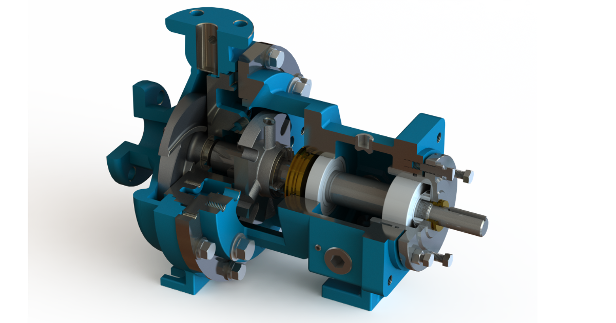
Hydraulic System: Impeller, Casing, Volute, and Diffuser
The hydraulic system converts mechanical energy from the motor into fluid energy. The impeller accelerates the liquid outward by centrifugal force. That velocity is partially converted into pressure inside the volute or diffuser. The result is the flow rate the pump can deliver at a given head, and it depends on both this system and the piping around it.
Impeller
The impeller is the part that most influences pump performance. Its diameter, type, material, and condition determine how much flow and pressure the pump can deliver.
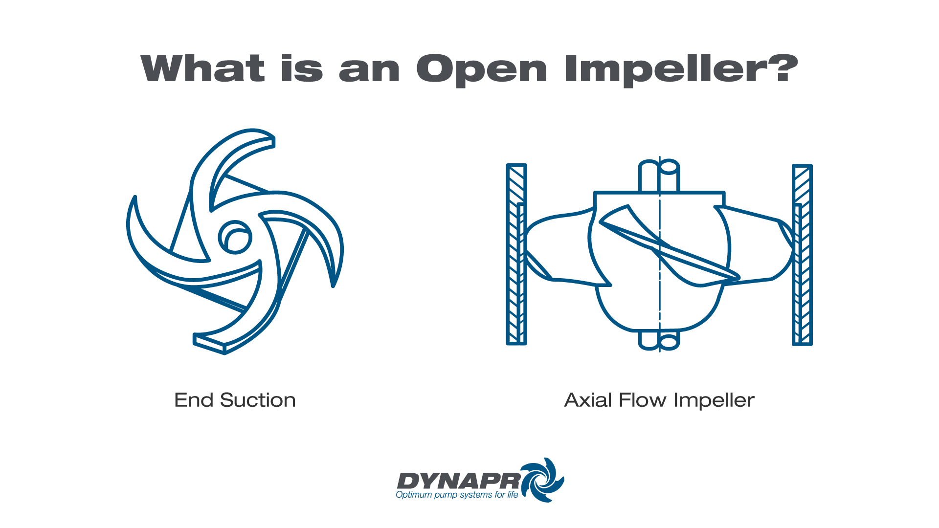
- Open: vanes without front or rear shroud. Handles solids and abrasive liquids. Wears faster and requires frequent clearance adjustment.
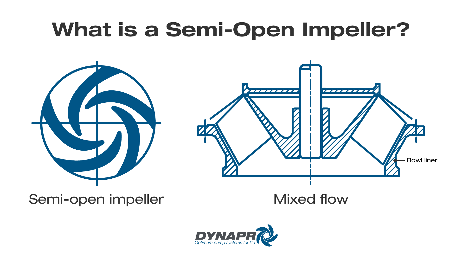
- Semi-open: rear shroud, no front shroud. Good balance between solids passage and efficiency.
- Closed: shrouds on both sides. Higher hydraulic efficiency, but susceptible to clogging with solids.
The material depends on the fluid: cast iron for clean water, stainless steel for corrosion, white iron or high-chrome for abrasive slurries. If you see pitting on the vanes, gravel-like noise during operation, and loss of flow, compare the available net positive suction head (NPSHa) against the manufacturer's required NPSH (NPSHr). That points to cavitation or insufficient suction margin, not necessarily a defective impeller. Replacing the impeller without correcting the root cause repeats the failure. Consult our cavitation guide for the full diagnosis.
Casing, Volute, and Diffuser
The casing serves two functions: structural support and flow guidance. The volute is the spiral passage that collects flow from the impeller and converts velocity into pressure. If the pump uses a diffuser instead of a volute (common in multistage pumps), that conversion occurs in fixed vanes around the impeller.
Erosion in the volute or diffuser typically appears in pumps that handle solids or operate far from BEP. When the casing shows circular rub marks near the impeller, the problem is not the casing: it is shaft runout or excessive bearing clearance that allows contact.
💡Tip: Before ordering a new casing for "wear," measure whether the erosion affects the volute geometry at the cutwater. Surface erosion that does not alter the hydraulic profile does not justify replacement. Polish and monitor.
Rotating and Drive System: Shaft, Coupling, Motor, and Baseplate
The motor delivers torque. The coupling transmits it to the shaft. The shaft turns the impeller. The baseplate keeps everything aligned. If something in this chain fails, the seals and bearings pay the price.
Shaft and Coupling
The shaft must do three things: transmit torque with deflection within the manufacturer's tolerance, keep the impeller centered, and provide proper support surfaces for the seal, sleeve, and bearings.
If the shaft has excessive runout in the seal area, the rotary face of the mechanical seal does not seat evenly. The result is immediate leakage and premature wear, even with a new seal. Measure runout with a dial indicator before installing any seal.
A misaligned coupling —angular, parallel, or combined— generates cyclic loading on the shaft. That load transfers to the bearings and seal. A check with a laser alignment tool or dial indicator before startup helps prevent avoidable downtime.
🔴Caution: A loose baseplate or one with soft foot misaligns the pump when the bolts are tightened. Never correct alignment with the baseplate distorted. First level the baseplate with shims, then align.
Motor and Baseplate
The motor is not an accessory: its selection and condition determine how much electrical energy reaches the fluid as useful work. A motor operating outside its efficiency range increases energy costs even if the pump delivers the correct flow rate.
The baseplate must be rigid, level, and correctly anchored. A flexible base amplifies vibration. If the base is properly installed but vibration persists, the source may be poorly supported discharge piping that transfers load to the nozzle. Check the pipe supports before blaming the pump.
Sealing and Support Systems: Seals, Shaft Sleeve, and Bearings
This is where pump reliability is won or lost. Seals, bearings, and the shaft sleeve are not accessories: they are the point where the five systems converge and where most unplanned shutdowns begin.
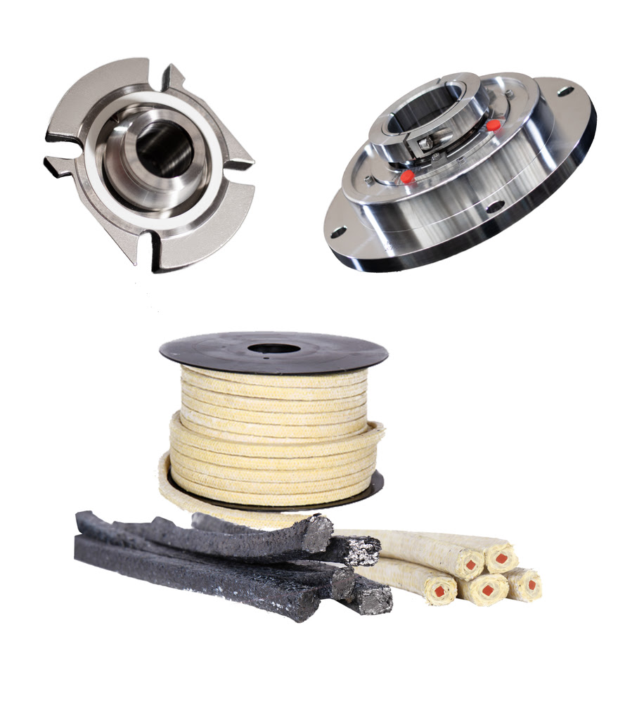
Mechanical Seal and Packing
The mechanical seal uses two polished faces —one rotary mounted on the shaft, one stationary in the casing— held in contact by spring force and hydraulic pressure. In normal operation, it should not show visible leakage, although a minimal lubrication film always exists between the faces.
Packing uses rings compressed around the shaft inside a stuffing box. It leaks by design to lubricate itself and dissipate heat. In fluids with solids or in large low-speed pumps, packing remains a valid option, especially if the environment punishes mechanical seal faces.
A seal leak does not always mean "damaged seal." It can come from:
- Shaft runout that misaligns the faces.
- Bearings with clearance that allow radial shaft movement.
- Insufficient flush or lubrication that overheats the faces.
- Abrasive fluid that wears the faces faster than expected.
- Dry running or air ingestion from poor suction conditions.
If you replace the seal and the leak returns within weeks, the problem probably was not just the seal. Review the steps to replace a mechanical seal without repeating the root cause.
Shaft Sleeve
The sleeve protects the shaft in the seal or packing area. If the sleeve surface is scored, corroded, or pitted, no replacement seal will perform properly. Check the sleeve condition every time you replace the seal. Replace it if there are visible marks, or repair the surface if the manufacturer allows reconditioning within tolerance.
Bearings
Bearings support radial loads (rotor weight, unbalance, hydraulic loads) and axial loads (impeller thrust). Incorrect lubrication —too much grease, too little, contaminated with water or particles— degrades them silently.
✓Decision Point: If the bearing housing temperature rises without explanation, do not add more grease immediately. Measure vibration and temperature with a thermometer or thermal imaging and compare against site trends. If vibration shows peaks at 1X, check for unbalance or misalignment before servicing the bearing.
Wear Parts: Rings, Plates, Gaskets, and Internal Clearances
Wear rings, side plates, and gaskets are neither cheap nor secondary parts. A wear ring clearance outside tolerance can increase energy consumption without the operator noticing anything other than "the pump is running."
Why Clearances Matter
Wear rings establish the separation between the high-pressure zone (discharge) and low-pressure zone (suction) of the impeller. When that clearance grows due to wear, abrasion, or corrosion, some of the fluid that already gained pressure recirculates back to the suction. The pump consumes similar power but delivers less useful flow.
The U.S. Department of Energy warns that pump efficiency can degrade between 10% and 25% before replacement, and that these inefficiencies are not always evident during operation. Internal leakage from excessive impeller clearances or worn parts reduces efficiency; corrective actions include restoring internal clearances and replacing or rebuilding wear rings, impellers, and throat bushings.
The DOE recommends identifying pumps operating 30% or more away from BEP or with system imbalances greater than 20% when looking for efficiency opportunities.
System Efficiency Formula
To quantify whether your pump is wasting energy, use the DOE formula:
$$ \eta_{sys} = \frac{Q_{req} \times H_{req} \times SG}{5308 \times P_e} $$
Where:
- \( Q_{req} \) = required flow rate in gpm
- \( H_{req} \) = total required head in ft
- \( SG \) = fluid specific gravity
- \( P_e \) = measured electrical input power in kW
- \( 5308 \) = unit conversion constant (gpm × ft × SG → kW)
Measure suction and discharge pressure, actual flow rate (with a portable meter if you do not have a fixed one), electrical input power in kW —or amperage along with voltage and power factor if you do not have a power meter— and fluid specific gravity. Compare the calculated efficiency against the original pump curve. An efficiency drop without a change in operating point points to increased internal clearances or internal recirculation.
Side Plates, Gaskets, and Throat Bushings
Side plates and throat bushings are sacrificial parts. They wear so the casing and impeller do not. Inspect them along with the wear rings and replace them when they are out of tolerance, eroded, or incompatible with the new fit.
Gaskets —casing, stuffing box, and flange gaskets— fail due to compression set, temperature, or chemical attack. A leaking casing gasket can be confused with a seal leak. Difference: casing gasket leakage runs along the casing split joint; seal leakage runs from the stuffing box.
How to Relate Field Symptoms to Components
A visible symptom on a part is usually the consequence, not the cause. Replacing the part without identifying what damaged it repeats the failure. Use this table to cross-check symptoms before taking action.
| Symptom | Likely Components | Field Evidence | Verification |
|---|---|---|---|
| Loss of flow and pressure | Worn impeller, excessive wear ring clearance, eroded volute | Progressive decline, not sudden | Compare Q/H against OEM curve; measure wear ring clearance; perform a full pressure diagnosis |
| Visible leak at stuffing box | Mechanical seal, shaft sleeve, packing | Dripping in seal area, stain on base | Measure shaft runout; inspect seal faces and sleeve surface |
| Gravel-like noise (cavitation) | Pitted impeller, poor suction, low NPSHa | Pitting on vanes, intermittent noise | Calculate NPSHa; check strainer, tank level, fluid temperature |
| High vibration at 1X | Impeller unbalance, bent shaft, misalignment | Vibration increases with speed | Check runout; balance impeller; align with laser |
| Vibration at multiple frequencies | Defective bearings, bearing clearance | Peaks in vibration spectrum; temperature rise in housing | Measure vibration with analyzer; compare trends; check lubricant |
| High bearing temperature | Poor lubrication, axial overload, damaged bearing | Dark/contaminated grease, temperature above trend or OEM limit | Verify lubricant type and quantity; review axial load from operation outside BEP |
| High current or power for the flow delivered | Operation outside BEP, impeller rubbing, internal recirculation from excessive clearances | kW or amperage above trend, with low useful flow or no process change | Measure Q, H, input kW, and efficiency; inspect for rubbing and clearances |
| Rub marks on casing | Excessive bearing clearance, bent shaft, excessive runout | Visible circular marks in impeller zone | Measure runout; check bearing fit |
⚠️Warning: A pump that vibrates, leaks, and consumes more energy to deliver the same flow at the same time probably has a systemic problem —severe misalignment, loose baseplate, or accumulated deterioration in several components— and not one failed part. Do not replace parts one by one; cross-check all symptoms before deciding on the corrective action.
Inspection Checklist Before Ordering Spare Parts
Before disassembling the pump or calling purchasing, gather this information. Arriving at the supplier with this data reduces quoting time and eliminates the risk of ordering a spare part that does not fit.
- ☐Nameplate data: manufacturer, model, serial number, year, casing material.
- ☐Operating data before failure: discharge pressure, measured or estimated flow rate, motor amperage, actual speed.
- ☐Pump curve: current operating point vs OEM curve. If you do not have the curve, request it from the manufacturer or supplier.
- ☐Fluid condition: type, temperature, presence of solids, abrasiveness, corrosiveness, pH.
- ☐Vibration: recent trends, current value, and spectrum if available.
- ☐Temperature: at bearing housing, casing, motor.
- ☐Visible leak: exact location, approximate leak rate, did it appear suddenly or progressively?
- ☐Visual inspection: photos of external condition, rub marks, corrosion, packing or seal.
- ☐OEM manual: clearance table, runout tolerances, tightening torque, lubricant type, and seal plan.
- ☐Maintenance history: date of last bearing, seal, ring, and lubricant change.
- ☐Lockout/tagout verified before any intervention (OSHA 29 CFR 1910.147).
If after gathering this information you need to confirm spare parts, materials, tolerances, or compatibility before working on a critical pump, contact us. Our application engineering team checks your data against manufacturer specifications so the spare part you order is the right one.
FAQs
What are the parts of a centrifugal pump?
They are grouped into five functional systems: hydraulic (impeller, casing, volute or diffuser), rotating and drive (shaft, coupling, motor, baseplate), sealing (mechanical seal or packing, shaft sleeve), support (bearings and housing), and wear parts (wear rings, plates, gaskets). Each system depends on the others.
What is the difference between casing and volute?
The casing is the complete structural body of the pump. The volute is the internal spiral passage that guides the flow from the impeller to the discharge flange and converts velocity into pressure. Every volute sits inside a casing, but not every casing contains a volute: some use a diffuser with fixed vanes.
Which component causes the most leaks?
The mechanical seal and packing are the first suspects, but the root cause of the leak may be in the shaft (runout), in the bearings (clearance that misaligns the seal faces), or in the sleeve (damaged surface). Before replacing the seal, check the condition of the surrounding components.
Which component causes the most vibration?
The most common cause is impeller unbalance or misalignment, followed by defective bearings and a loose baseplate. A single vibration value without a spectrum is not enough: the dominant frequency (1X, 2X, vane pass) points to different components. Consult our pump curves guide for more detail on radial loads and BEP.
Which parts wear the most?
Wear rings, the shaft sleeve, the packing or seal faces, and the impeller (especially in fluids with solids). Gaskets also degrade with temperature and tightening cycles. The wear rate depends on the fluid, alignment, lubrication, and how far from BEP the pump operates.
How do I know which spare part to order?
At minimum, you need nameplate data (manufacturer, model), OEM component reference, physical dimensions (diameter, fit, material), and clearance tolerance if applicable. Without the OEM part number, any serious supplier will return the inquiry asking for that data.
---
References
- U.S. Department of Energy - Pumping Systems Tip Sheet #4: Test for Pumping System Efficiency
- ISO 2858:1975 - End-suction centrifugal pumps (rating 16 bar)
- ISO 5199:2002 - Technical specifications for centrifugal pumps, Class II
- ANSI/HI 14.1-14.2-2024 - Rotodynamic Pumps for Nomenclature and Definitions
- OSHA 29 CFR 1910.147 - The control of hazardous energy (lockout/tagout)
- U.S. Department of Energy - Pump Systems
- API Standard 610, 12th Edition - Centrifugal Pumps for Petroleum, Petrochemical, and Natural Gas Industries (paywalled)
- API Standard 682, 4th Edition - Pumps: Shaft Sealing Systems for Centrifugal and Rotary Pumps (paywalled)


